C1629M-F (3/08) 27
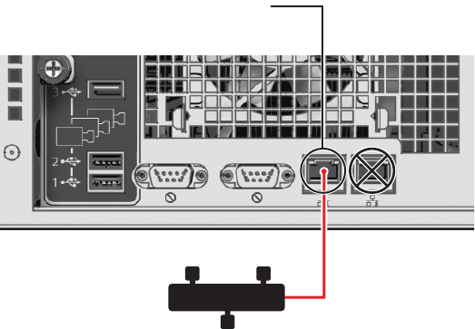
Figure 22. Network Cable Connection
2. Connect the other end of the UTP cable to an available port on a Pelco-approved Gigabit Ethernet switch. Contact Pelco’s Product Support
for a list of approved Gigabit Ethernet switches (refer to Appendix F: Troubleshooting on page 43 for contact information).
There are two indicators on the network connector on the rear panel. The right indicator glows orange when there is a good connection
between the DVR5300 and a Gigabit Ethernet switch that is powered up. If the indicator does not glow, check the cable and the switch.
Disregard the left indicator, which shows network activity.
NOTE: Do not power up any DVR5300 system component (ENC5300, network, camera control) until you have connected all components.
CONNECTING SERIAL PTZ DEVICES
NOTE: Pelco recommends using the Coaxitron up-the-coax camera control protocol, which simplifies installation and does not require any
additional equipment. For information on implementing Coaxitron on the DVR5300, refer to the ENC5300 Series Installation manual (C1625M).
The DVR5300 supports Pelco D (four-wire) and Pelco P (two-wire) protocols. These protocols use a serial interface to transmit commands to the
PTZ device over separate control wires. When the DVR5300 receives a camera control command, it transmits that command to the PTZ device.
The system continues receiving video over the coaxial cable through the ENC5300.
You can install multiple camera control lines in a star configuration. Run all control lines from each device to a CM9760-CDU-T code distribution
unit (CDU) in a central location. Then connect the CDU to the DVR5300. The maximum length for each pair of control lines is 4,000 feet (1,219 m).
The CDU only supports two-wire (unidirectional) operation for Pelco D and Pelco P.
NOTES:
• When using serial PTZ devices, do not mix protocols on the same control chain.
• All serial PTZ devices require at least two wires (RX+ and RX-). If a device is bidirectional, you have to run two additional wires to the
device (TX+ and TX-).
To connect serial PTZ devices to a DVR5300 using a star configuration (refer to Figure 23):
1. Connect twisted pair wiring from the RX+ and RX- on each PTZ device to the TX+ and TX- leads on a specific channel on the CM9760-CDU-T
(refer to the CM9760-CDU-T Installation/Operation manual [C1940M]). The maximum length is 4,000 feet (1,219 m).
PRIMARY NETWORK
CONNECTOR
ENDURA NETWORK
