


C695M-B (11/03) 7
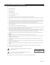
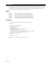
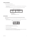
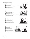
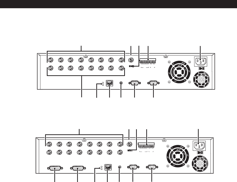
Figure 2. DX3108 Rear View
1
IN
OUT
23456
78
NTSC PAL
IN OUT ALARM
G1234G 1 2
230V115V
115V
123456
78
LAN
RC
P/T/Z SERIAL
ᕨᕧᕩᕦᕫᕵ
ᕡᕤᕥᕢᕣ
ᕫᕾ
MON OUT
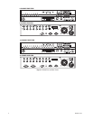
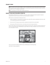
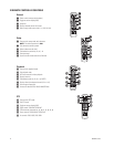
Figure 3. DX3116 Rear View
ᕡ Channel inputs: 16 for DX3116, 8 for DX3108; 8 looping outputs for DX3108
ᕢ Monitor out BNC connector
ᕣ NTSC/PAL selection switch (default is NTSC)
ᕤ Alarms: 4 dry contact inputs and 2 relay outputs
ᕥ AC power input (default is 115V)
ᕦ Serial port (reserved)
ᕧ PTZ port (PTZ control of cameras using Pelco’s P or D protocol)
ᕨ RC (connection for optional external receiver for IR remote controller)
ᕩ Network port (10/100BASE-TX Ethernet)
ᕫᕾ Network indicators: Red LED for connection, green LED for network activity
ᕫᕵ Looping outputs 1-8
ᕫᕶ DX3116 only: Looping outputs 9-16
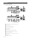
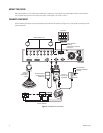
INSTALLATION
DX3100 REAR PANEL CONNECTIONS
The rear views of the DX3108 and DX3116 are shown in Figures 2 and 3, respectively.
1
IN
23456
78
NTSC PAL
IN OUT ALARM
G1234G 1 2
230V115V
91011121314
15 16
LAN
RC
P/T/Z SERIAL
OUT9-16OUT1-8
115V
ᕫᕶ
ᕡᕢᕣ ᕥ
ᕦᕧᕨᕩᕫᕾᕫᕵ
ᕤ
MON OUT