C2673M-D (8/10) 19
Hardware Setup
BASIC CONNECTIONS
NOTE: Refer to the KBD300USBKIT Installation manual for information about installing the KBD300A keyboard.
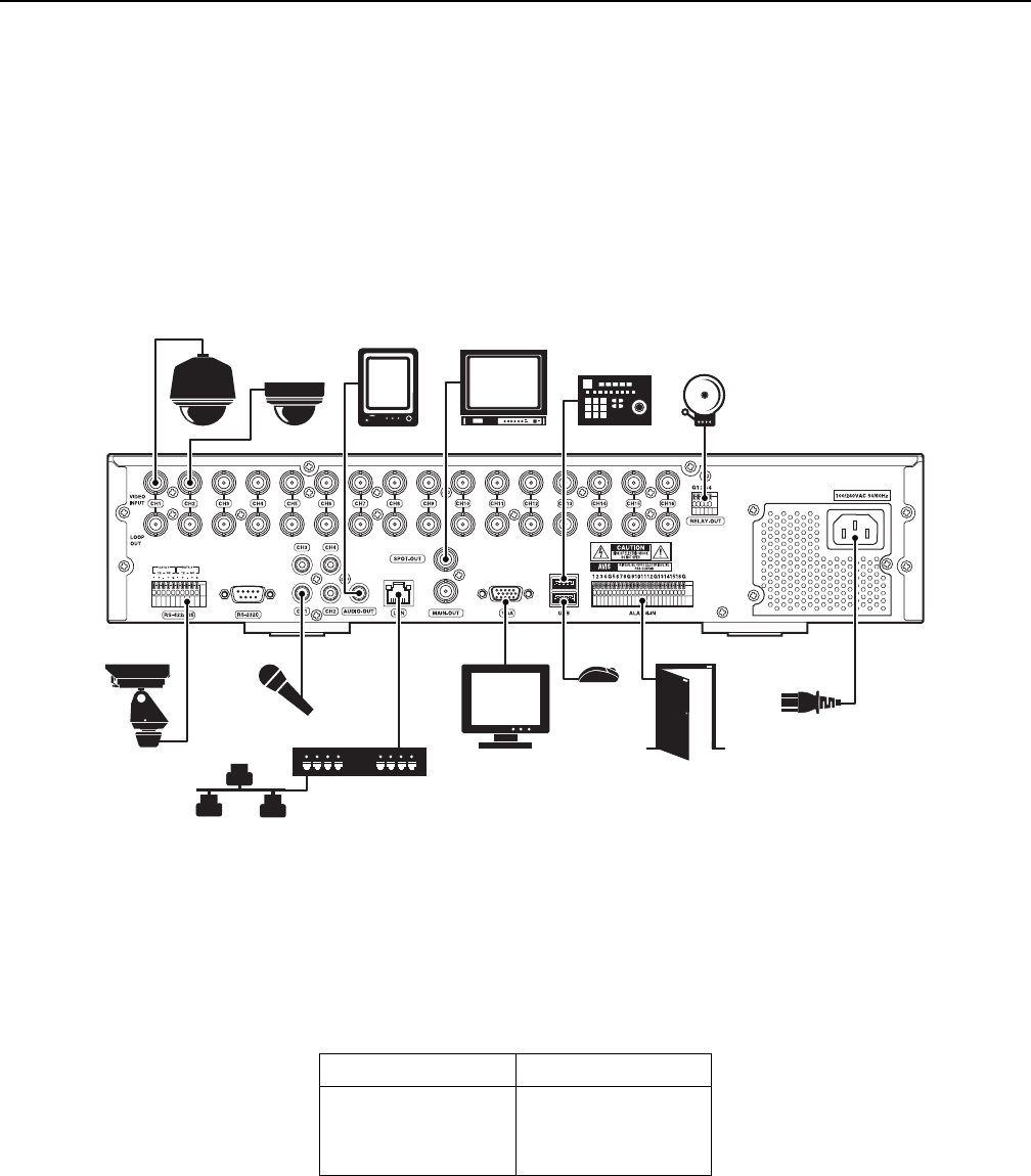
To make the basic equipment connections to the DX4500/DX4600, refer to Figure 8 and do the following:
1. Connect the USB mouse to the bottom USB connector. The mouse allows you to operate the DVR using the GUI and on-screen PTZ control.
2. Connect a VGA monitor (not supplied).
3. Connect the cameras to the BNC connectors. Refer to Table D for video coaxial cable requirements. Connect power to the cameras.
4. Connect the appropriate power cord to the back of the unit and to a power source. The DX4500/DX4600 contains an autoranging power
supply. It is recommended that the recorder be connected to an uninterruptible power supply (UPS) capable of supplying 2 A for 120 VAC
power systems or 1 A for 230 VAC power systems.
Figure 8. Basic Connections
NOTE: You might experience operational issues when a camera device is not correctly terminated. When connecting camera devices, use a
normal load termination of 75 ohms. When looping through DVR inputs, ensure that the signal is terminated at the end device. For additional
information about terminating a specific camera device, refer to the device’s installation manual.
The following table describes the coaxial cable requirements.
Table D. Video Coaxial Cable Requirements
Cable Type* Maximum Distance
RG59/U
RG6/U
RG11/U
750 ft (229 m)
1,000 ft (305 m)
1,500 ft (457 m)
*Cable requirements:
75-ohms impedance
All-copper center conductor
All-copper braided shield with 95% braid coverage.
