20 C2673M-D (8/10)
CONNECTING PTZ CAMERAS
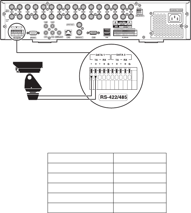
PTZ devices can be connected to the DX4500/DX4600 using the two RS-422/RS-485 ports located on the back of the unit: DATA 1 and DATA 2.
PTZ camera control is achieved by using the respective protocol for that camera. For information about configuring the DVR to communicate with
the PTZ device, refer to the DX4500/DX4600 Operation/Configuration manual.
DX4500/DX4600 support for PTZ camera connection is summarized as follows:
• 8-channel DVRs supports up to 8 serial PTZ cameras
• 16-channel DVRs supports up to 16 serial PTZ cameras
• Maximum distance for serial communication lines is 4,000 ft (1219 m)
• Multiple PTZ cameras are connected by daisy-chaining the camera connections
To connect a PTZ camera to the DX4500/DX4600:
1. Using a small screwdriver (or similar tool), push in the DATA 1 TX- terminal block retainer.
2. Insert the RX- serial data line from the PTZ camera into the TX- connector, and then release the terminal block retainer.
3. Verify that the RX- data line is securely fastened to the TX- terminal block.
4. Repeat steps 1 through 3 to connect the RX+ data line.
Figure 9. Connecting PTZ Camera Serial Communication Lines
The following table describes the RS-422/RS-485 ports.
Table E. Data Port Descriptions
RS-422/RS-485 Terminal Description
TX - (DATA -) Data Transmission
TX + (DATA +) Data Transmission
RX - (DATA -) Data Reception
RX + (DATA +) Data Reception
GND Shield
