


SOUND MENU CONTROLS (CONTINUED)
+
-
+-
L
R
S-VIDEO-1 S-VIDEO-2
ANT A / CABLE
75⍀ UHF/VHF
R
L
PIP
ANT B / CABLE
75V UHF/VHF
REAR SURROUND
EXT. SPEAKERS
AUDIO
OUT
VIDEO
OUT
AUDIO INPUT
AUX 1 AUX 2
AUX 1 AUX 2
VIDEO INPUT
AUDIO OUT
VAR PIP
RR
LL
– 8⍀ +
1
L
R
S-VIDEO-1 S-VIDEO-2
ANT A / CABLE
75⍀ UHF/VHF
R
L
PIP
ANT B / CABLE
75V UHF/VHF
REAR SURROUND
EXT. SPEAKERS
AUDIO
OUT
VIDEO
OUT
AUDIO INPUT
AUX 1 AUX 2
AUX 1 AUX 2
VIDEO INPUT
AUDIO OUT
VAR PIP
RR
LL
– 8⍀ +
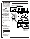
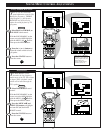
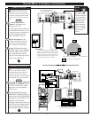
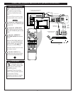
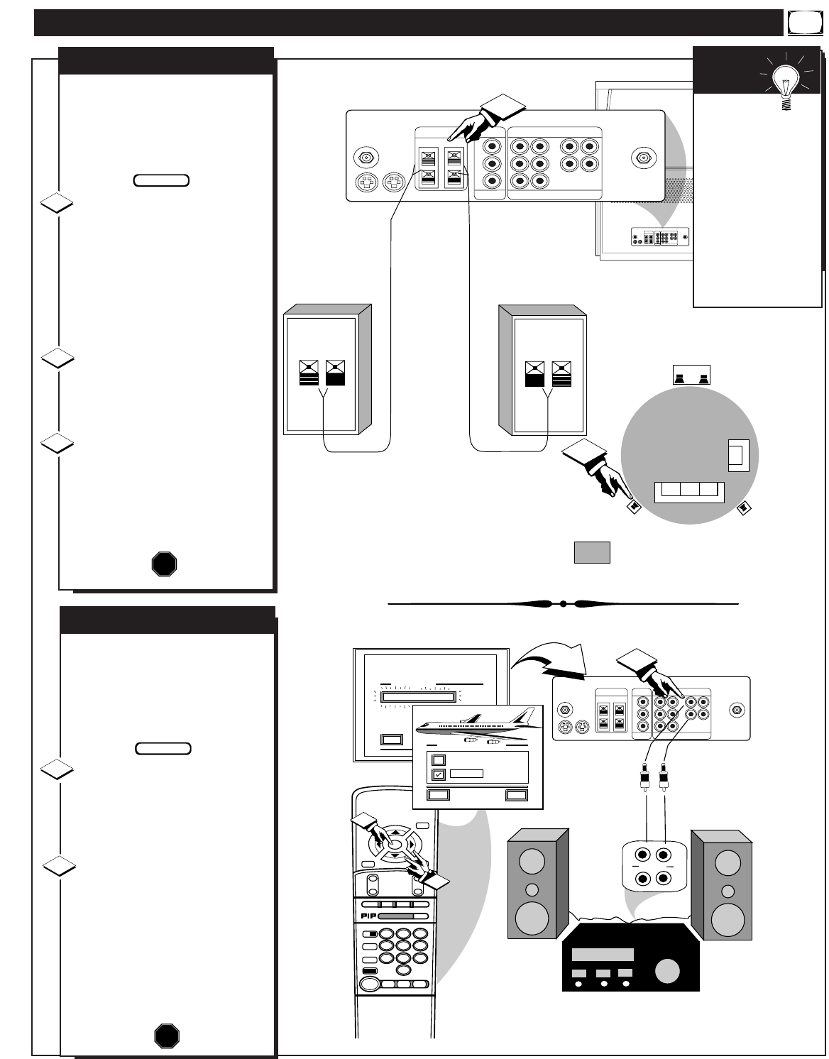
SURROUND SOUND
B
y adding optional external
speakers to the TV's sound
system, you can create the feeling
of reflected sound that surrounds
you at a movie theater or concert
hall.
Connect both external
speakers to the speaker wire
terminals on the TV.
Recommended speakers: 8ohm, 15
watt minimum. Be sure the (+) and
(-) speaker wires are connected to
the correct R(ight) and L(eft)
speaker terminals on the TV.
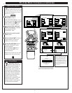
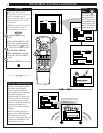
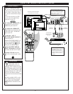
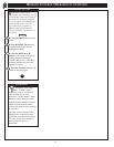
Place the speakers so the
viewing area is between the TV
and the rear surround speakers.
(See overhead view drawing.)
Turn TV ON and place the
STEREO control to the "STEREO
IF AVAILABLE" (ߜ) position.
After setup whenever a stereo
signal is received the audio will be
heard in Surround Sound.
STOP
1
2
3
BACK OF TV
REAR SURROUND SOUND SPEAKERS
Note: The rear Surround Sound speakers will not
be heard at the same volume level as the front TV
speakers. It is intended for the rear speakers to give
a background noise effect which requires a lower
volume level than the TV's front speakers.
2
PRIMARY VIEWING AREA
TV
REAR SPEAKER
REAR SPEAKER
BEGIN
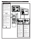
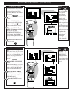
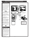
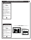
VARIABLE AUDIO OUTPUT
T
he TV's Variable Audio Output
jacks can also be used for
Surround Sound. Once they are
connected to an external hi-fi
system its speakers can be used for
the playback of Surround Sound.
Connect the R(ight) and L(eft)
VARIABLE AUDIO OUT jacks
on the TV to the R and L Audio
Input jacks on your amplifier or
sound system.
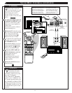
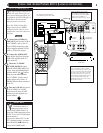
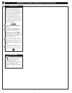
Turn TV ON and place the
VARIABLE AUDIO OUTPUT on
screen control to the SURROUND
(ߜ) position. (Sound Menu 3 of 3).
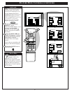
Note:This will change the
Left/Right channel audio line level
signal at the Audio Output jacks to
the same signal found at the TV's
Surround Sound Speaker terminals.
STOP
1
2
BEGIN
L
R
S-VIDEO-1 S-VIDEO-2
ANT A / CABLE
75⍀ UHF/VHF
R
L
PIP
ANT B / CABLE
75V UHF/VHF
REAR SURROUND
EXT. SPEAKERS
AUDIO
OUT
VIDEO
OUT
AUDIO INPUT
AUX 1 AUX 2
AUX 1 AUX 2
VIDEO INPUT
AUDIO OUT
VAR PIP
RR
LL
– 8⍀ +
STOP ■
REW
ᮤᮤ
FF
ᮣᮣ
PLAY
ᮣ
REC ●
STATUS
VOL
CH
1
2
3
4
5
6
7
8
9
0
ON/OFF
TV/VCR
VCR
CBL
TV
SWAP
FREEZE
POS
SIZE
ENTER
M
E
N
U
M
CLEAR
SURF
MUTE
PAUSE II
SLEEP
SMART
POWER
M
ODE
LIGHT
2 TUNER PIP
B
ᮤ
ᮤ
A
SOUND MENU
EXIT
3 OF 3
VARIABLE AUDIO OUTPUT
MORE...
AUX/TV INPUT
PHONO INPUT
L
R
VARIABLE AUDIO OUTPUT
HELP
EXIT
STEREO
SURROUND
1
2
2
AUDIO SYSTEM SPEAKERS USED AS REAR
SURROUND SOUND SPEAKERS
BACK OF TV
REAR SURROUND SOUND
SPEAKER TERMINALS
VARIABLE AUDIO
OUTPUT JACKS
AUDIO
INPUT JACKS
Remember,
Surround Sound
will not work with
only one speaker
connected; or with
monaural audio
material (unless
Stereo Surround
control is turned
ON - see Variable
Audio section
below).
SMART
HELP
27