


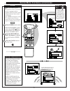
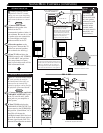
USING THE AUDIO/VIDEO INPUT JACKS (CONTINUED)
VIDEO OUT
AUDIO OUT
L
R
FIXED
VAR
PIP
ANT A/CABLE
75 ⍀ UHF/VHF
INPUTS
VIDEO
AUDIO
AUX 1 AUX 2
R
L
ANT B/CABLE
75 ⍀ UHF/VHF
PIP
S-VIDEO
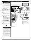
EXIT
1 OF 3
PICTURE
SOURCE
MORE...
CLOSED
CAPTIONS
FEATURE MENU
CHANNEL
MEMORY
CABLE
TUNING
1
PICTURE SOURCE SELECT
HELP
EXIT
ANT A
AUX 1 S-VIDEO
AUX 2 VIDEO
SIDE VIDEO
ANT B
AUX 1 Y P
B
P
R
2
OUT
AUDIO
R
L
S-VIDEO
OUT
VIDEO OUT
Y
P
P
B
R
VIDEO 1
VIDEO 2
OUT
Y
P
B
P
R
5
4
STOP ■
REW
ᮤᮤ
FF
ᮣᮣ
PLAY
ᮣ
REC•/
STATUS
VOL
CH
1
2
3
4
5
6
7
8
9
0
ON/OFF
TV/VCR
VCR
ACC
TV
SWAP
FREEZE
POS
SIZE
ENTER
M
E
N
U
M
CLEAR
SURF
MUTE
PAUSE II
SLEEP
SMART
POWER
M
O D E
2 TUNER PIP
B
ᮤ
ᮤ
A
VCR
Plus +
3
3
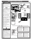
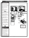
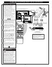
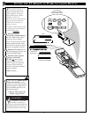
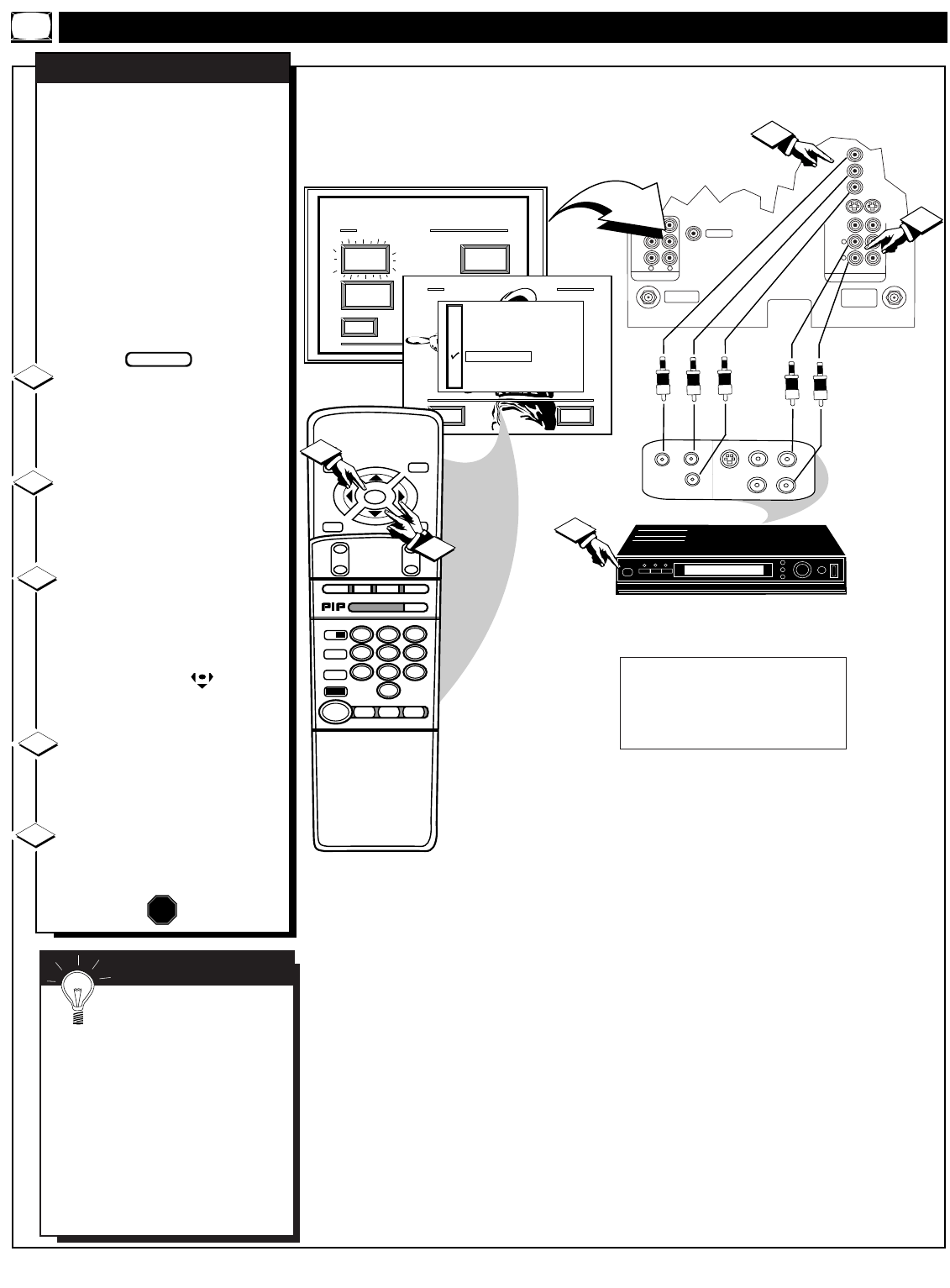
C
omponent Video Inputs
provide for the highest
possible color and picture
resolution in the playback of
digital signal source material such
as with DVD players. The color
difference signals (PB, PR) and the
luminance (Y) signal are
connected and received separately
which permits for improved color
bandwidth information (not
possible when using composite
video or S-Video connections).
Connect the Component (Y PB
PR) VIDEO OUT jacks from the
DVD player to the (Y PB PR)
VIDEO IN(put) jacks on the TV.
Connect the AUDIO OUT
jacks R(ight) and L(eft) from the
DVD player to the AUX 1 AUDIO
IN jacks on the TV.
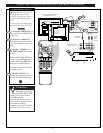
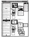
Select the "AUX 1 Y PB PR"
PICTURE SOURCE control on
the TV.
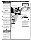
With the FEATURES MENU on
screen, move the RED highlight
with the MENU (M) buttons.
Then press the MENU button.
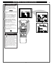
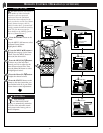
Press the MENU ▲▼ and
MENU (M) buttons to highlight
and select (ߜ) the AUX 1 Y PB PR
mode.
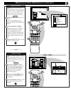
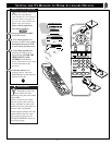
Turn the DVD player ON and
press PLAY to view the source
material playback on the TV.
COMPONENT VIDEO INPUTS
1
2
3
4
STOP
COMPONENT
VIDEO OUTPUTS
AUDIO OUT (L/R)
(RED/WHITE)
Optional Video/Audio Cables (with standard
RCA plug connectors) are available to
complete your Component Input Jack
connections. Contact your dealer, or our Parts
Information Center (1-800-851-8885) to order
any optional accessories.
DVD PLAYER
(equipped with Component Color
& Luminance Outputs)
PICTURE AND SOUND FROM PLAYBACK
OF DVD SOURCE MATERIAL
BEGIN
5
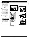
SMART HELP
The description for the
component video connectors
may differ depending on the DVD
player or accessory digital source
equipment used (e.g. Y PB PR; R-Y/B-
Y/Y; Cr/Cb/Y, etc.). Although
abbreviations and terms may vary, the
letters “B” and “R” stand for the blue
and red color component signal
connectors and “Y” indicates the
luminance signal. Refer to your DVD
or digital accessory Owner’s Manual
for definitions and connection details.
36
BACK OF TV