


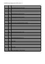

ISSUE
DRAWING NO.
DRAWING TITLE
DATE
Filename:
ECO No. DESCRIPTION OF CHANGE
L924TX_1.0.sch
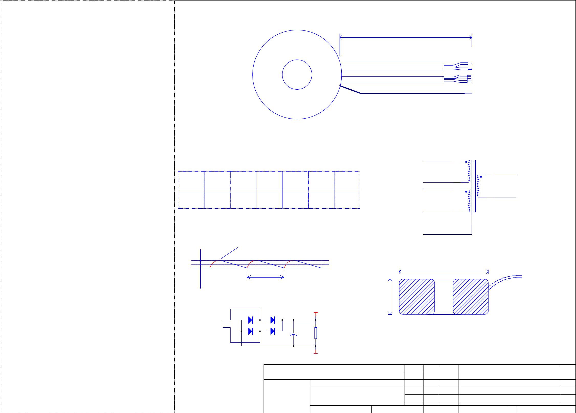
DV78 TRANSFORMER 115/230V
Contact Engineer:
L924TX
7-Jul-2003
INITIALS
Printed:
1 1Sheet of
Notes:
Contact Tel: (01223) 203243Kevin Lamb
A & R Cambridge Ltd.
Pembroke Avenue
Cambridge CB5 9PB
Waterbeach
ARCAM
A3
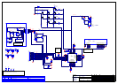
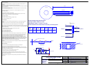
+
1360uF
TEST CIRCUIT
+VOUT
AC IN
Prototype Release
Voltage on Reservoir Capacitor
10mS
A.04-12-2003KAL
Vmin
Voltage
115V
115V
6
4
2
1
5
3
7
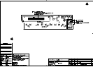
TX1
Small Toroidal Mains
L924TX
GREY
WHITE
BLACK
BLUE
RED
RED
PRIMARY SECONDARY
Transformer Specification for 115/230V 50/60Hz mains transformer.
Arcam Part Number L924TX
The transformer is extremely cost sensitive. It is to employ the most cost effective techniques to achieve the
specification.
The transformer output voltage will be regulated by a switch mode power supply.
The only essential specification is the fact that it must produce no acoustic noise either internally or by induced eddy
currents in steel chassis etc..
All other specifications are negotiable in the interest of allowing cost reduction. Even the use of a frame TX rather
than a toroid is negotiable providing it is silent.
1. The transformer MUST be silent when loaded to Po +10% and when supplied from Vin = 270V r.m.s.
General Safety specification.
---------------------------------------------------
2. To standards BS415 / EN60065 - Class I / EN60742
3. Transformer to be used in equipment which will be sold worldwide and certified to CE, CB, UL and CSA
Standards. All materials etc to be adequate for worldwide safety approvals.
Material Safety Specification
---------------------------------------------------
4. Winding Wire to be Grade 2 (130°C rating) to BS 60317-4 1995
5. Mylar Polyester Insulator Rated to 130°C
Electrical Specification
---------------------------------------------------
6. Transformer to have dual 115V primaries to allow parallel operation for 115V input and series operation with
230V input.
7. Transformer is required to provide a mains isolation barrier and provide a single secondary winding.
8. The secondary winding is to be full wave rectified and smoothed as shown in the below diagram.
9. The DC voltage so provided will be followed by a switch mode power supply which will provide a constant power
load.
(i.e. the current drawn by the load will increase as the DC output voltage falls- hence the capacitor ripple voltage will
be higher at low input voltage)
10. The power drawn by the load has a maximum continuous rating (Po) of 22W.
11. Transformer input voltage range as follows:
115V (85V to 132.5V) windings in parallel
230V (170V to 265V) windings in series
Note. Extended input voltage range 85V to 265V
12. At minimum input voltage (170V AC) the minimum voltage on the capacitor must be > 22.5V with Po = 22W
13. At maximum input voltage and minimum load of 6W the max voltage on output capacitor must be < 63V.
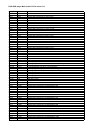
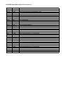
14. The secondary voltages and r.m.s currents have been calculated and are tabulated against input voltage.
The model assumes the transformer regulation is made as poor as possible while meeting spec.
The equivalent series resistance of the windings transformed to the secondary is 7ohms under this condition.
Rms figures for voltages and currents are true rms figures measured with the specified bridge rectifier, Capacitor
and load resistor connected to the transformer secondary.
In the case of the load regulation for lowest cost transformer being better than the worst case specification then the
transformer voltages shall be modified so that the minimum 22.5V spec is met at 170V input and the output
voltages at 230V and 265V input voltage are lower than the specified voltages.
15. Temperature rise to be such that transformer is safe when operated in an enclosure with 50C maximum internal
temperature.
16. Toroid to be fitted with interwinding screen.
Mechanical Specification
---------------------------------------------------
17. Primary wires self-ended and individually sleeved for colour coding, then sleeved together.
18. Secondary wires self-ended and individually sleeved, then sleeved together.
19. Wire type used on the terminations must be such that the wire may be bent with a miniumum bend radius of
10mm through an angle of 90degrees 10times without the wire fracturing. This will allow the wires to be dressed in
production without risk of damage to terminations.
20. All wire lengths are +20, -0 mm. All wires stripped 8 +/-2mm and tinned.
21. Transformer to be marked with part number and issue number.
22. Toroidal transformer will be attached to the chassis by a dished washer and bolt (no potting required).
23. A frame transfomer meeting the above spec will be chassis mounted with flying leads and should have clamp
fitted to allow it to be screwed to chassis.
24. Toroidal transformer to be supplied with mounting kit consisting of metal dished washer and 2 neoprene or
similar washers.
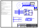
PRIMARIES
80mm dia max
SCREEN WIRE
40mm max
LEADS EXIT NEAR TOP
330MM
TOP VIEW
SECONDARY
GREEN/YELLOW
GND
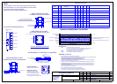
AC Supply
170
230
265
(V r.m.s.)
Voltage
Secondary
23.2
37.3
44.4
Peak Voltage
Capacitor
26.9
46.0
55.7
(Volt)
Min Voltage
Capacitor
23.7
43.7
53.8
Average
Capacitor
25.3
44.8
54.8
to simulate
Load Resistor
Load RL
28
88
130
Secondary
Winding r.m.s.
Current
1.3
0.86
0.75
(V r.m.s.) (Ohm)(Volt) (Volt) (A r.m.s.)
Voltage
63V
RL see above table.
Secondary Winding Voltage and Current Specs
Vpk Vmin
Vpk
assuming C=1360uF, f= 50Hz for Po = 22W
Vaverage
Ideal TX assumed with 7Ohm series resistor in secondary to simulate regulation.
Bridge Rectifier Vf diode = 1.1V per leg = 2.2V Total
Vf = 1.1V
per diode
SCREEN WIRE
02_E336
GREEN/YELLOW
Reduced Power Output Spec, Reduced Load Regulation Spec A.14-02-2003KAL
Loaded
37.3V
03_E042
Corrected Wire Colours added notes re Clamp B.021-03-2003KAL03_E086
Pri in Series
Production Release 1.002-07-2003KAL03_E195