


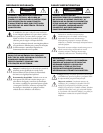
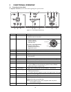
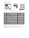
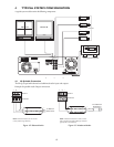
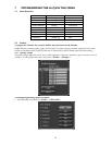
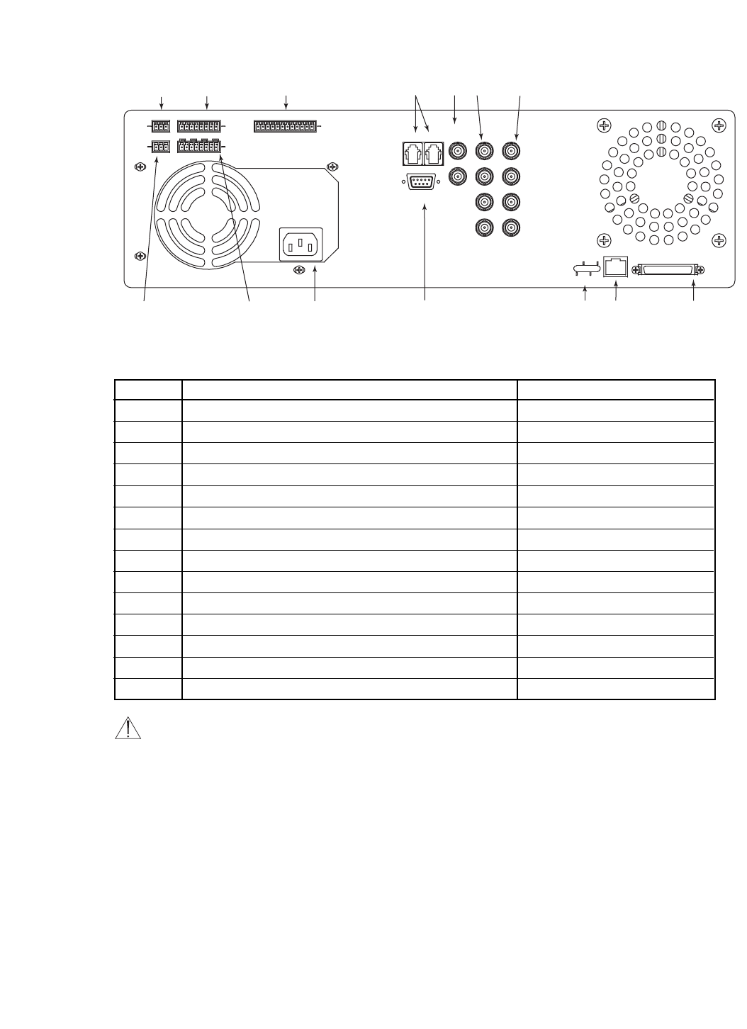
3.2 Rear Panel of the Hi-Q
Figure 3.2 Rear Panel of the Hi-Q
NOTES:
• Unused camera inputs should be disabled via the menu to avoid Vid Loss alarm.
• Each alarm input and output corresponds to the physical camera input/output channel (i.e., input #1 corresponds
to camera #1).
11
CAMERA
1
MONITOR
A
LOOP
KEYBD
B
2
3
4
AUDIO
IN
AUDIO
OUT
ALARM
IN
RELAY
SDA
CONSOLE
RX
TX
COL
100
ETHERNET
SCSI
+ S –
+ S –
1 S 2 S 3 S 4 0
1 2 3 4
+ S – + S – + S – + S –
1
2
3
4
5
6
7
8
9
10
11
12
13
14
Ref Description Connector Type
1 AUDIO IN Screw terminal
24 ALARM INputs
**
Screw terminal
3 SDA biphase output for PTZ cameras
* **
Screw terminal
4 Keyboard loop-through and keyboard input
*
RJ-11
5 MON A and B outputs BNC
64 video inputs 75 Ω autoterminating BNC
74 video looping ports 75 Ω autoterminating BNC
8 AUDIO OUT Screw terminal
94 RELAY outputs (N/O or N/C)
**
Screw terminal
10 Auto-sensing power input (110/220 VAC, 50/60 Hz) IEC male
11 CONSOLE RS-232
*
/CCL port DB-9 male
12 Ethernet status lights
13 Ethernet 10/100BaseT RJ-45
14 SCSI connector for archiving device 50-pin high density D
* Functionality provided with software upgrade in later release.
** Belden 8760 twisted shielded cable (or equivalent) should be used for wiring to the alarm connector. Total length of
unshielded cable not to exceed 10 cm (3.9 in) on each connector port to maintain compliance with Directive 89/336/EEC.