


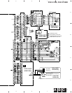
DVD-V7400, DVD-V7300D
21
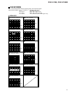
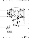
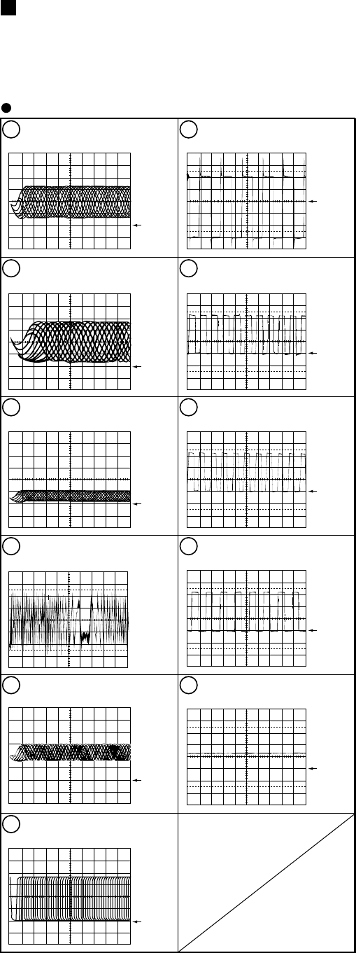
WAVEFORMS
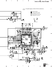
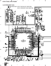
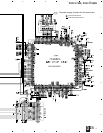
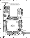
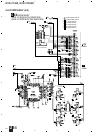
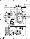
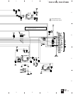
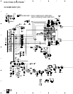
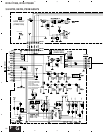
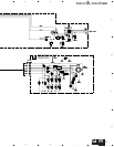
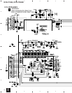
DVDM ASSY
Note : The encircled numbers denote measuring point in the schematic diagram.
Measurement condition : No. 1 to 4 and 6 to 11 : Disc MA1, Title 1-chp 1
No. 5 : CD, ABEX-784 Track 1
No. 12 to 14 : MJK1, Title 1-chp 4 or T2-1
No. 15 to 17 : MJK1, Title 1-chp 5 or T2-19
No. 18 to 20 : T2-19, Color-bar (WY and WV Types only)
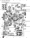
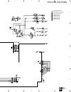
1
Foot of R169 (RF)
V: 100mV/div. H: 0.2µsec/div.
2
CN201 - pin 5, 6 (RFO)
V: 500mV/div. H: 0.1µsec/div.
3
IC701 - pin 170 (MY CHIP input)
V: 1V/div. H: 0.2µsec/div.
4
CN201 - pin 9, 10 (Tracking Error)
(AI-Inner Tracking Off)
V: 500mV/div. H: 2msec/div.
5
IC201 - pin 39 (EFM before slice)
V: 1V/div. H: 1µsec/div.
6
IC201 - pin 1 (EFM)
V: 1V/div. H: 0.2µsec/div.
7
Q281 - Collector (FG)
V: 1V/div. H: 5msec/div.
8
Foot of R261 (FPWM)
V: 1V/div. H: 5msec/div.
9
Foot of R262 (VPWM)
V: 1V/div. H: 5msec/div.
10
Foot of R263 (PPWM)
V: 1V/div. H: 5msec/div.
11
Foot of R264 (RPWM)
V: 1V/div. H: 5msec/div.
GND
GND
GND
GND
GND
GND
GND
GND
GND
GND