


52
DVD-V7400, DVD-V7300D
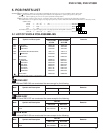
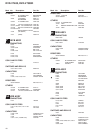
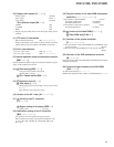
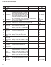
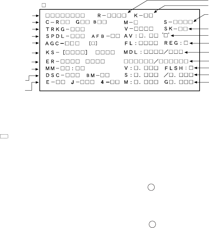
• Description of Each Item on the Display
(1) Address indication
The address being traced is displayed in number.
DVD : ID indication (hexadecimal number, 8 digits)
[ ∗ ∗ ∗ ∗ ∗ ∗ ∗ ∗ ]
CD : A-TIME (min. sec.) [ 0 0 0 0 ∗ ∗ ∗ ∗ ]
(Note : For DVDs, decimal-number indication is possible.)
(2) Code indication of the remote control unit
[R – ∗ ∗ ∗ ∗]
The code for the key pressed on the remote control unit, which is
received by the FL controller, is displayed while the key is pressed.
In the case of the double code, the second code will be displayed.
(3) Key code indication for the main unit [K – ∗ ∗ ]
The code for the key pressed on the main unit, which is received by
the system controller, is displayed while the key is pressed.
(4) Background color indication [C – R∗ ∗ G∗ ∗ B∗ ∗]
(5) Tracking status [TRKG – ∗∗∗]
Tracking on [ON ]
Tracking off [OFF]
(6) 1 Spindle status [SPDL – ∗ ∗ ∗]
Spindle accelerator and brake, free-runnimg [A/B]
FG servo [FG]
Rough, velocity phase servo [SRV]
Offset addition, rough, velocity phase servo [O_S]
2 AFB status [AFB – ∗ ∗]
ON [ON ]
OFF [OFF]
(7) Mechanism position value [M – ∗]
Position code [1] to [3]
(8) Slider position [S – ∗ ∗ ∗ ∗]
CD TOC area [IN ]
CD active area [CD ]
(9) AGC setting [AGC – ∗ ∗]
AGC on [AGC-ON]
AGC off [AGC-OFF]
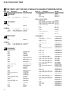
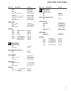
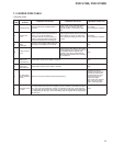
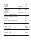
Remote control code
Key code
Mechanism position value and
slider position
Output video system and
Skirt terminal output
FL controller version and
region setting for the player
Port No. of Flash ROM and
system controller
System controller revision
Flash ROM version and Flash ROM size
FL controller destination setting
AV1 chip version
DVD mechanism controller revision
(Control and part No. of GUI-ROM)
Character in bold : Item name
: Information display
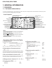
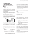
First Screen Display
• Screen Composition
Address
Background color
Tracking status
Spindle status and AFB status
AGC setting
FTS servo IC information
C1 error value of CD and DVD
Internal operation mode of
the mechanism control
Disc judgment and
CD 1/3 beam switch
Equalizer value and
jitter value
Consecutive double-OSD display is supported during test mode. The screen is composed 10 lines with a maximum of 32 characters per line.
It can't be used with the debugging display mode together.
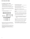
Caution :
•The first screen and second screen switch by pressing [DISPLAY]
key of the remote control unit.
•It is only a version display part on the lower right of the screen
those contents of display change.
•MDL: V730/ (All modells of DVD-V730,DVD-V7400 and DVD-
V7300D are displayed like the left.)
•The displays of Tilt error value, Tilt servo status and pickup
DVD/CLD display deleted .
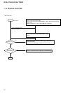
7. GENERAL INFORMATION
7.1 DIAGNOSIS
7.1.1 TEST MODE SCREEN DISPLAY