


14
En
English
Installation and Connections
Installation and Connections
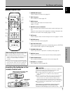
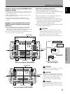
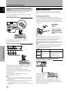
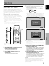
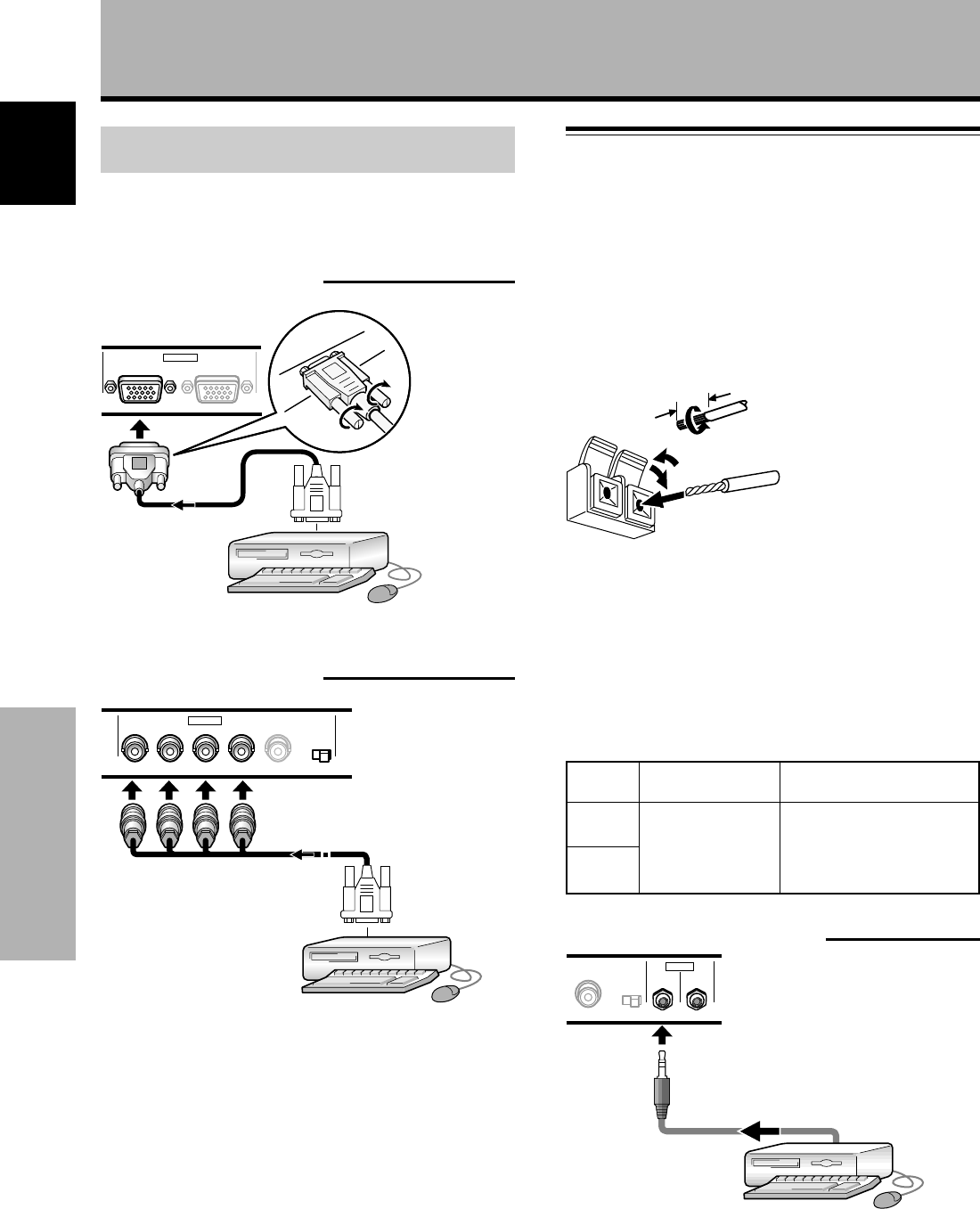
Connection of composite SYNC analog RGB
source
Make composite SYNC connections for a personal
computer with output that has the vertical
synchronization signal layered on top of the horizontal
synchronization signal.
When connecting to INPUT1
ANALOG RGB (ANALOG RGB)
INPUT1
OUTPUT
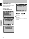
On-screen setup is necessary after connection.
Please see pages 17 and 18.
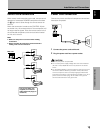
When connecting to INPUT2
GBRHDVD
(ON SYNC) (H/V SYNC)
Ô
75 2.2
Ω kΩ
INPUT2
When using INPUT2, set the impedance selector switch
to match the output impedance of the connected
computer’s synchronization signal.
When the output impedance of the computer’s
synchronization signal is below 75 Ω, set this switch to
the 75 Ω position.
On-screen setup is necessary after connection.
Please see pages 17 and 18.
Notes
÷ When making composite SYNC connections, do not connect
anything to the VD jack. If connected, the picture may not be
displayed properly.
÷ On some types of Macintosh
®
components, G ON SYNC and
composite SYNC are both output. With this type of
component, please connect using the G ON SYNC connection
(see page 13).
Audio Connections
Before making connections, be sure to check that the
audio component’s power and the unit’s main power is
off.
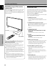
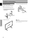
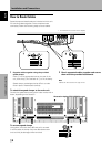
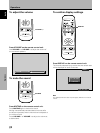
Connecting the speakers
This unit is equipped with speaker output jacks for
connection to the speaker system (not supplied) specially
designed for use with this unit. Refer to the illustrations
below when making connections to the speaker terminals
on this unit.
10 mm
Note
When making speaker connections, be sure to match the
polarities (+ and –) of the speaker terminals on this unit and the
corresponding terminals on the speakers. If the polarity is
reversed, the sound will be unnatural and lack bass.
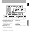
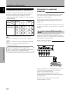
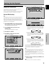
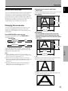
Making connections to the audio inputs on this
unit
This unit features two audio inputs and one audio output.
The following chart shows the video inputs and the
corresponding audio input jacks.
Twist exposed
wire strands
together.
Push tab to the open
position, and insert the
wire. Then, close tab
firmly to secure the wire
in place.
INPUT1
INPUT2
Audio input jacks Sound output
Stereo mini jack
(L/R)
Sound of the selected video
input is output from the
• SPEAKER terminals
• Stereo mini jacks (L/R).
Video
input
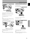
Audio connections for component (computer)
connected to INPUT 1 or INPUT 2
VD
Ô
75 2.2
Ω kΩ
INPUT
(INPUT1/2)
OUTPUT
AUDIO
Audio input to the
AUDIO INPUT jacks
(stereo mini jack) is
possible for a
component connected to either INPUT1 or INPUT2.
Sound is output from both the AUDIO OUTPUT jacks
(stereo mini jack) and the SPEAKER terminals according
to the video input selection.