


Connecting up
02
52
En
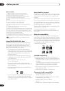
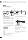
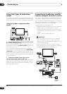
Using other types of audio/video
output
If you can’t use the SCART AV connector to connect your
TV to this recorder, there are standard audio/video output
jacks, as well as an S-video and component video output.
Using the S-video or component video
output
1 Connect the S-video or component video output
to a similar input on your TV.
For an S-video connection, use an S-video cable (not
supplied) to connect the S-VIDEO OUTPUT jack to an S-
video input on your TV.
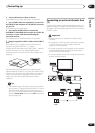
For a component video connection, use a component
video cable (not supplied) to connect the COMPONENT
VIDEO OUT jacks to a component video input on your TV.
See also Component Video Out on page 129 for how to set
up the component video output for use with a progressive
scan-compatible TV.
2 Connect the AUDIO OUTPUT jacks to the
corresponding audio inputs on your TV.
You can use the supplied audio/video cable, leaving the
yellow video plug disconnected. Make sure you match up
the left and right outputs with their corresponding inputs
for correct stereo sound.
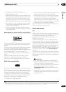
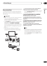
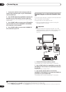
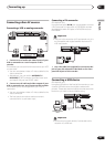
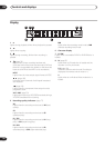
Connecting to a cable box, satellite
receiver or digital terrestrial receiver
If you have a cable, satellite or digital terrestrial receiver
with a built-in decoder, connect it to this recorder and
your TV as shown on the following page.
1
If you are using
a separate decoder box for your cable/satellite TV, set up
following the instructions on the next page.
Using the setup on this page you can:
• Record any channel by selecting it on the cable box,
satellite receiver or digital terrestrial receiver.
• Change channels and set timer recordings on the
external receiver using the GUIDE Plus+™ system
(via the
G-LINK™ cable, and after setting up).
Important
• Do not connect this recorder to your TV ‘through’
your VCR, satellite receiver or other component.
Always connect each component directly to your TV
or AV amplifier/receiver.
• When using the GUIDE Plus+ system to make a
timer recording from an external receiver, make sure
that the external receiver is switched on.
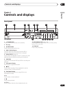
TV
AC IN
DIGITAL
OUT
CONTROL
G-LINK
COAXIAL IN
S-VIDEO
VIDEOAUDIO
L
R
COMPONENT
VIDEO OUT
Y
P
B
PR
ANTENNA
IN
OUT
OUTPUT
AV 1 (RGB) – TV AV 2 (INPUT 1/DECODER)
S-VIDEO
INPUT
COMPONENT
VIDEO INPUT
AUDIO
INPUT
1
2
Note
1 The diagram shows SCART video connections, but you can alternatively use any of the other audio/video connections.
TV
Satellite dish/
antenna/cable TV
wall outlet
Cable/Satellite/
Digital Terrestrial
receiver
AC IN
DIGITAL
OUT
CONTROL
G-LINK
COAXIAL IN
S-VIDEO
VIDEOAUDIO
L
R
COMPONENT
VIDEO OUT
Y
P
B
PR
ANTENNA
IN
OUT
OUTPUT
AV 1 (RGB) – TV AV 2 (INPUT 1/DECODER)
SCART AV
CONNECTOR
SCART AV
CONNECTOR
ANTENNA
IN
ANTENNA
IN (RF IN)
ANTENNA
OUT
ANTENNA
OUT
ANTENNA
IN
1
1
2
3
1
4