


Chapter 3 - Operation AMC-101
Installation & Operation Manual
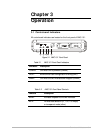
3-2 Controls and Indicators
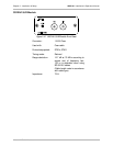
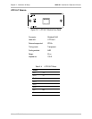
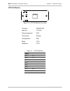
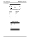
Power Supply
AC
DB-9 Connector
(ALARM)
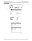
JP2
JP1
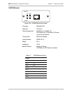
AMC-RELAY
(ALARM)
Card
JP1
JP4
JP2
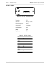
GND
JP6
JP7
VCC
ERR-CFG
IDLE-EN
AMC-101
Module
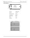
AMC-101
Module
LEDs Card
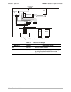
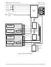
Figure 3-2 Jumper Locations and Functions
Table 3-3 Functions and Settings
Jumper ID Function Conditional Setting
JP2 ERR-CFG Mounted (Factory Default)
JP7 Idle-Enable If mounted, idle will be transmitted when no signal
is received from the other side. Not mounted
(Factory Default)