


AMC-101 Installation & Operation Manual Chapter 3 - Operation
Dry Contact Circuit and Connector for Alarms 3-3
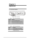
3.2 Cable Connections
Grounding
DC adapter Connection.
Note
In order to protect the AMC-1 from electrostatic discharge (ESD), use a DC
adapter where the (-) DC pole is connected to the protective earth.
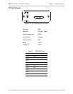
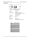
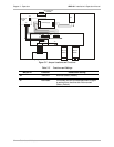
3.3 Dry Contact Circuit and Connector for Alarms
A dry circuit with a 9-pin D-type connector on the rear panel, has been
added to the unit to signal minor and major alarms. The dry contact circuit
is used to signal the following alarms:
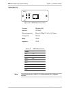
Alarm type Description
RED ALARM Power Failure (DC voltage on board)
YELLOW ALARM Signal Detect Failure (to any of the unit modules)
CONFIG ALARM Improper Configuration (incompatible modules
and/or data rates selected)
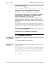
Three pins are dedicated for each alarm: Common (COM), OK and FAIL.
The COM pin is the input for each alarm. The user can drive the COM pin
with any signal (0 to 5v). If the signal is received OK, the COM pin is
connected to its corresponding OK pin; If there is a failure, the COM pin is
connected to its corresponding FAIL pin. See Table 3-4 and Figure 3-3 for
the connector pin assignments.
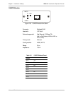
Table 3-4 Connector Pin Assignment
Alarm Type COM OK FAIL
RED 9 4 5
YELLOW 3 8 7
CONFIG 6 2 1
Figure 3-3 Connector Pin Assignment