


RR1 • 6
of the one second time frame (0.60 seconds total of the entire second). For a
logical zero, the LED will still be switched on and off at a rate of 38 kHz, but
this time only for 30% of the total time (0.30 seconds total of the entire sec-
ond).
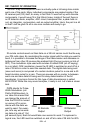
When the IR detector “sees” a 38 kHz IR signal, the output of the detector
goes low (it is inverted). Conversely when there is no 38 kHz carrier signal
present, the output idles high. If you were to look at the output of the IR detec-
tor you wouldn’t see the original 38 kHz carrier present, just the logical data
that the PWM 38 kHz represents from your IR remote control. If we want to re-
send this data, we have to modulate a 38 kHz carrier again in accordance with
the data the IR detector puts out. There are a number of different ways we
could do this. One possibility is to turn a 38 kHz oscillator on and off using the
IR detector output as the switch, this lends itself to the problem of how fast our
oscillator can start up and settle however. A better idea is to go one step fur-
ther and use a micro-controller to generate the 38 kHz carrier. The data output
from the IR detector can be sampled by the micro-controller which in-turn gen-
erates a 38 kHz carrier signal that is Pulse Width Modulated (PWM) according
to the detected data.
By using this method with a micro-controller, we can add some intelligence
to the regenerated signal as well. The sample IR remotes we have looked at
send their data at a rate of around 2400 bits per second. This means that our
minimum pulse length for a zero should be 1/2400 x 0.30 seconds long (125
uS). Consider this example, let’s say that the signal from the IR remote is
weak and it fades out due to interference from some other IR source before
the data pulse is finished (i.e. 80 uS instead of 125 uS). The micro-controller
will continue to send the 38 kHz until 125 uS is up, not allowing the re-
transmitted signal to drop out the way the original source did. This error cor-
rection feature can be disabled in case you have a strange remote that is not
compatible (to this point we have yet to run across one that doesn’t work). Re-
move the jumper from J2 to disable this feature and have U1 blindly re-create
the data it sees.
Once the micro-controller has re-generated your 38 kHz carrier (modulated
by the data), we buffer its output with transistor Q1 to drive the IR LED. The
current through the IR LED is limited by R1 and is typically around 50 mA.
This is pretty hard for an LED but don’t worry. Even though the steady ‘on’
state of a typical IR LED can only handle about 20 mA, we are switching the
LED on and off at 38 kHz during the entire send sequence. The LED may be
on only about 50% of the total time to send the data. To achieve the maximum
transmission range and peak performance from the system, we’ve cranked up
the current a bit to get More Power!!!!