


-E9-
34
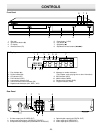
CHANNEL
TO TV ANT. IN
R-AUDIO-LVIDEO
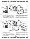
A/V INPUT JACKS
VHF/UHF
ANTENNA
IN
Y
RL
P
B
P
R
AUDIO OUT
VIDEO OUT
COMPONENT VIDEO OUT
VIDEO OUT
SELECT
S
COMPONENT
S-VIDEO OUT
1
2
3
4
34
CHANNEL
TO TV ANT. IN
R-AUDIO-LVIDEO
A/V INPUT JACKS
VHF/UHF
ANTENNA
IN
34
CHANNEL
VHF/UHF
FROM ANT.
IN
OUT
TO TV
Y
RL
P
B
P
R
AUDIO OUT
VIDEO OUT
COMPONENT VIDEO OUT
SUBWOOFER
OUT
VIDEO OUT
SELECT
S
COMPONENT
S-VIDEO OUT
3
4
1
2
5
5
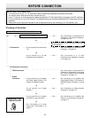
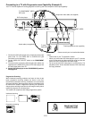
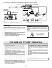
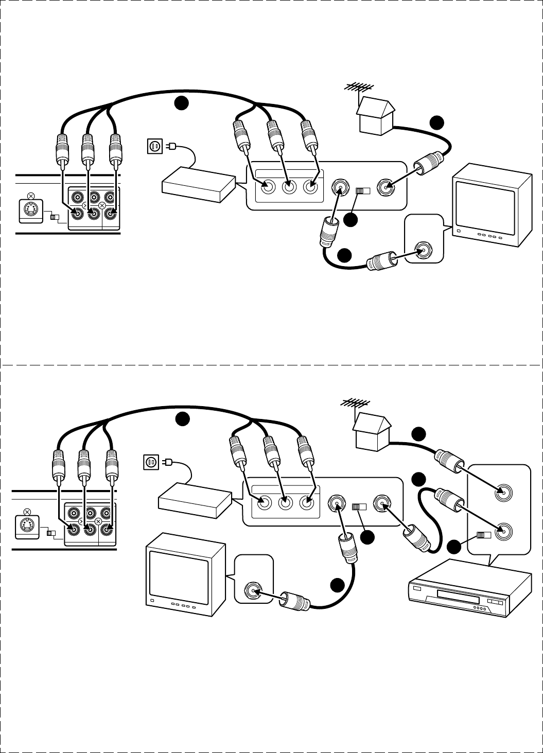
Using RF Modulator
If your TV does not have a Video input jack and has an antenna
terminal only, please purchase the *RF Modulator (not supplied).
(*Please consult your audio/video dealer.)
Example: DVD video player, TV and RF Modulator connections
1. Connect the antenna cable (not supplied) to the ANT. IN
terminal of the RF Modulator.
2. Connect the 75-ohm coaxial cable (not supplied) between
the TO TV terminal of the RF Modulator and the VHF/UHF
ANTENNA IN terminal of the TV.
3. Connect the Audio/Video cable (supplied) between the
AUDIO OUT and VIDEO OUT jacks of the DVD video
player and the AUDIO INPUT and VIDEO INPUT jacks of
the RF Modulator.
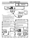
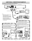
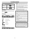
Example: DVD video player, VCR, TV and RF Modulator connections
1. Connect the antenna cable (not supplied) to the VHF/UHF
FROM ANT IN terminal of the VCR.
2. Connect the 75-ohm coaxial cable (not supplied) between
the TO TV OUT terminal of the VCR and the ANT. IN
terminal of the RF Modulator.
3. Connect the 75-ohm coaxial cable (not supplied) between
the TO TV terminal of the RF Modulator and the VHF/UHF
ANTENNA IN terminal of the TV.
4. Connect the Audio/Video cable (supplied) between the
AUDIO OUT and VIDEO OUT jacks of the DVD video player
and the AUDIO INPUT and VIDEO INPUT jacks of the RF
Modulator.
5. Turn on the TV, and set the channel number (CHANNEL3 or
CHANNEL4) on all TV, VCR and RF Modulator, whichever
is not used for regular broadcasts in your area.
Note:
For more details, please refer to the instruction manual of the RF
Modulator.
4. Turn on the TV, and set the channel number (CHANNEL3 or
CHANNEL4) on both TV and RF Modulator, whichever is not
used for regular broadcasts in your area.
Note:
For more details, please refer to the instruction manual of the RF
Modulator.
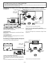
TV
(White) L
To AUDIO
OUT jacks
(Red) R
TV
VCR
RF Modulator
Audio/Video cable (supplied)
(White) L
(Red) R
To audio input
jacks
(White) L
(Red) R
Audio/Video cable (supplied)
To audio input
jacks
(White) L
(Red) R
RF Modulator
To AC 120V,
60Hz
DVD video player
To AC 120V,
60Hz
DVD video player
To VIDEO OUT jack
(Yellow)
To VIDEO OUT jack
(Yellow)
To AUDIO
OUT jacks
To video input
jack
(Yellow)
To video input
jack
(Yellow)