


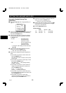
CONNECTIONS
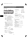
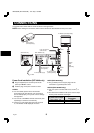
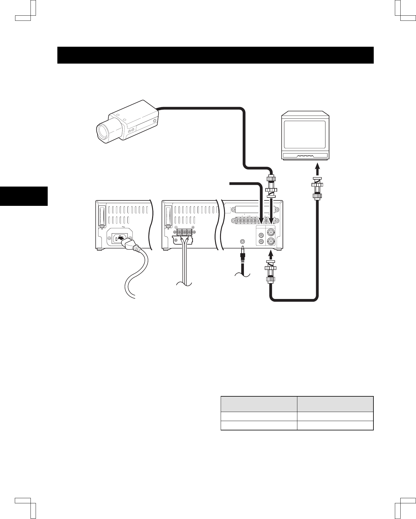
Connect the video camera and TV monitor as shown in the figure below.
NOTE:
Before making the connections, make sure the devices are disconnected from the power outlet.
AUDIO VIDEO
OUT
OUT
IN
IN
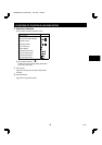
REMOTE
OPEN COLLECTOR
ALARM(1 SHOT)IN SERIES IN 3
COM
CONTROL OUT 3
CONTROL IN 3 WARNING OUT 1
EXT TIMER
(ALARM RESET) IN
TAPE END OUT 2 SW OUT
TIMER OUT 3
1=500mA(Max.)
2= 50mA(Max.)
3=SEE MANUAL
PUSH
OPEN
To remote control
(sold separately)
Video camera
(sold separately)
TV Monitor (sold separately)
Coaxial
cable
(sold
separately)
To
VIDEO
IN
jack
To
VIDEO
OUT
jack
From an external
audio source
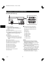
AC IN
PUSH
OPEN
Power cord
To outlet
DC power cord
(not supplied)
To DC power supply
SRT-4040 only SRT-4040DC only
DC 12-24V IN
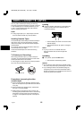
Power Cord Installation (SRT-4040 only)
1
Plug the supplied power cord firmly into the AC
power input AC IN ~ socket.
2
Insert the plug of this power cord into a outlet.
NOTES:
œ For more details, please refer to the manuals
accompanying all other devices. If the connections
are not made properly, it may cause a fire or damage
the equipment.
œ You can use a VA-RMN01 Remote Control Unit (sold
separately) to control the VCR remotely.
œ If there is no video signal when the power is turned
on, “NO VIDEO” will be displayed on-screen.
NOTE (SRT-4040 only):
œ The grounded power cord (3-pin plug) must be
connected to a grounded power outlet.
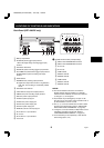
NOTES (SRT-4040DC only):
œ Use a DC power cord rated A.W.G 18 (1.25 mm
2
) or
more.
œ The table below indicates the DC power source output
and DC power maximum cord lengths.
DC power source output
DC power maximum
cord lengths
18 V or more 2 A 6 m
12 ~ 16 V 3 A 6 m
NB4QR/NA (SRT-4040 GB) Tue. Sept., 10/2002
English
9