


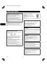
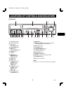
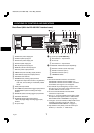
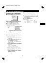
CONNECTIONS
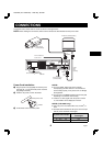
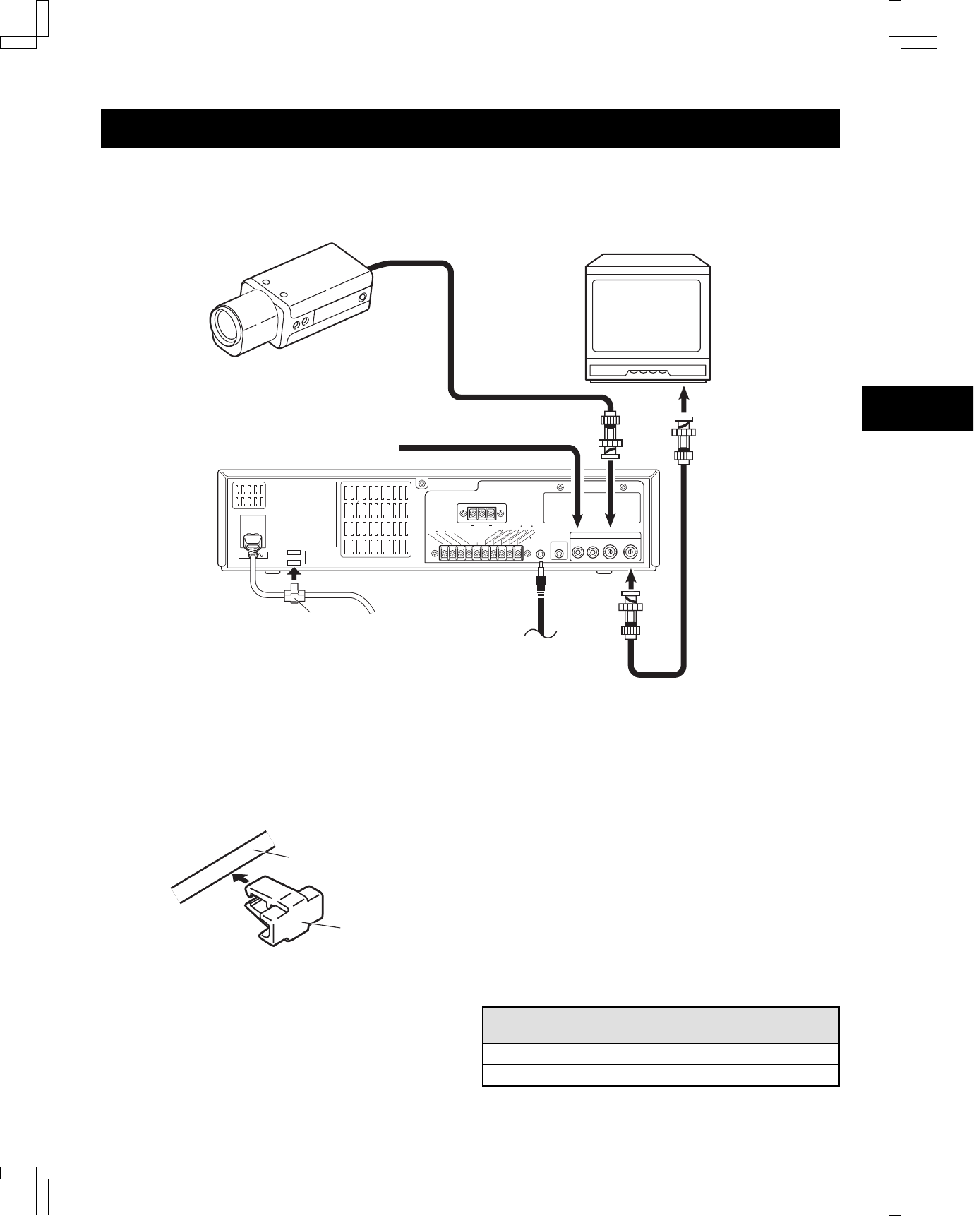
Connect the video camera and TV monitor as shown in the figure below.
NOTE:
Before making the connections, make sure the devices are disconnected from the power outlet.
RS232C
TERMINATE
Do not connect to phone line.
OFF ON
RS485 BA
AC IN
AUDIO VIDEO
ININ OUTOUT
REMOTE
MIC IN
SW
O
UT
W
ARN
I
N
G
OU
T
1
E
X
T
TIMER
IN
S
ERIES IN
C
ONT
R
O
L
IN
AL
ARM
(
1
SHOT) IN
(
A
L
A
R
M R
E
S
E
T
)
CON
T
R
OL
OU
T
T
A
PE E
ND
OU
T
T
I
M
E
R
OU
T
COM
2
OPEN COLLECTOR (Max. 1=500mA, 2=50mA)
SEE MANUAL
DC12-24V IN
To remote control
(sold separately)
Video camera
(sold separately)
TV Monitor (sold separately)
Coaxial
cable
(sold
separately)
To
VIDEO
IN
jack
To
VIDEO
OUT
jack
From an external
audio source
Power cord
To outlet
Holder
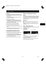
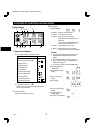
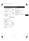
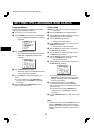
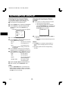
Power Cord Installation
1
Plug the power cord (supplied) into the AC power
input (AC IN ~) on the VCR back panel. Insert the
plug straight and firmly.
2
Insert the AC power cord into the holder.
3
Fix the holder to the VCR back panel.
Holder
AC power cord
NOTES:
œ For more details, please refer to the manuals
accompanying all other devices. If the connections
are not made properly, it may cause a fire or damage
the equipment.
œ You can use a VA-RMN01 Remote Control Unit (sold
separately) to control the VCR remotely.
œ If there is no video signal when the power is turned
on, “NO VIDEO” will be displayed on-screen.
NOTES (TLS-1960P only):
œ Use a DC power cord rated A.W.G 18 (1.25 mm
2
) or
more.
œ The table below indicates the DC power source output
and DC power maximum cord lengths.
DC power source output
DC power maximum
cord lengths
18 V or more 2 A 6 m
12 ~ 16 V 3 A 6 m
RQ4Q/EX (TLS-1960P GB) Wed. May, 08/2002
8
English