


12
Operating Instructions
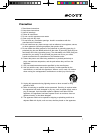
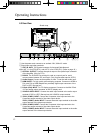
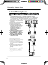
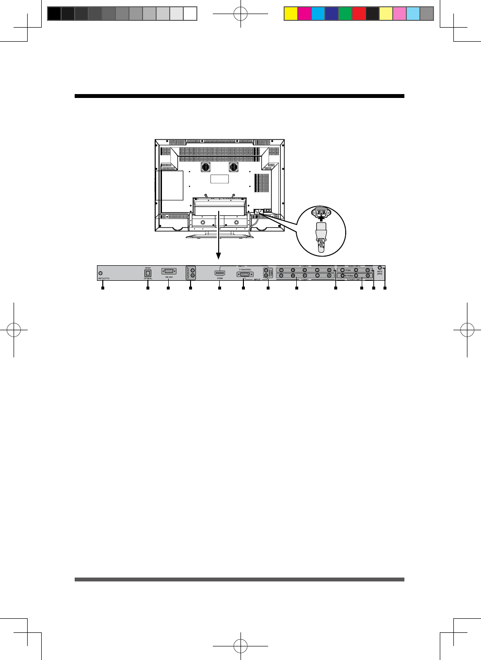
Use the power cord connect to an earthed 120V, 60Hz AC outlet.
Signal input and other terminals:
ANT1 & ANT2:75ΩCoaxialconnectorforAntenna/CableNetwork
.
Note: ANT 1 is for ATSC(DTV), and ANT 2 is for NTSC(ATV). (Refer to page 19.)
OPTICAL OUTPUT: Connect the optical output to the optical input connector
oftheAmplier.(OnlyforDTV)
RS-232: The D-SUB 9 Pins terminal is used as a control port for serial
communication
between PC and Panel. (Only for after-sales service & DTV)
Audio Output:ConnectaudioamplierorotherTVsetthatwithaudioinput.
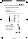
HDMI INPUT: For high quality picture display purposes. Connects to HDMI or
DVI (with DVI to HDMI Adapter-not provided) digital output connector of the
DVD or HDTV Set-top box.
D-Sub (VGA) INPUT: For PC display purposes. Connects to the Mini D-Sub
15 Pins analog output connector of the PC display card.
VGA/DVI AUDIO INPUT: Connect the audio input terminal to the audio output
terminal
of DVD or HDTV Set-top box with VGA/DVI output terminal.
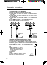
YPbPr (COMP1) INPUT: Connect the Component video input terminal to the
Component
output terminal of the video output device.
YPbPr
(COMP1) Audio INPUT: Connect the audio input terminal to the audio
output terminal of the video output device.
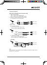
YPbPr (COMP2) INPUT: Connect the Component video input terminal to the
Component
output terminal of the video output device.
YPbPr
(COMP2) Audio INPUT: Connect the audio input terminal to the audio
output terminal of the video output device.
4.3 Rear View
Sketchmap