


SETUP
–
8
–
EN
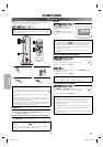
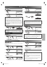
Connection to a TV
CAUTION:
• Be sure to turn off the unit and equipment to be connected before connecting.
• Read through the Operation Manual for the equipment to be connected.
• Be sure that the colors of the jacks and plugs match up when connecting the cable.
• Be sure to keep the unit connection cables separate from the TV antenna cable when you install the unit, because it may cause electrical
interference when you are watching television programs.
CAUTION:
• Connect the unit directly to the TV. Do not connect the unit to a VCR, then con-
nect the VCR to the TV. Copyright protection in the VCR could distort the picture
playing on the unit.
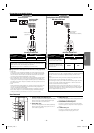
DV-MX1
PROGRESSIVE
LABEL-SIDE
STOP
POWER
PLAY
EJECT
T V
This unit
VCR
LCR / PR
CB / PB
Y
R
AUDIO
OUT
VIDEO
OUT
COMPONENT
VIDEO OUT
DIGITAL
AUDIO OUT
COAXIAL
CB
Y
C
R
COMPONENT
VIDEO IN
or
PB
Y
P
R
AUDIO IN
LR
LCR /
C
B /
Y
R
AUDI O
OUT
VIDEO
OUT
COMPONENT
VIDEO OUT
DIGITAL
AUDIO OUT
COAXIAL
L
R
AUDIO
OUT
DIGITAL
AUDIO OUT
COAXIAL
VIDEO IN
L Y
R
AUDIO
OUT
VIDEO
OUT
DIGITAL
AUDIO OUT
COAXIAL
LCR / PR
CB / PB
Y
R
AUDIO
OUT
VIDEO
OUT
COMPONENT
VIDEO OUT
S-VIDEO
OUT
DIGITAL
AUDIO OUT
COAXIAL
S-VIDEO IN
T V
This unit
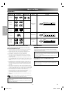
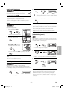
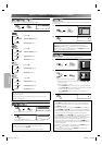
Method 1
Good picture
Method 2
Better picture
Method 3
Best pictureBasic Audio
(Analog) AUDIO OUT VIDEO OUT S-VIDEO OUT COMPONENT VIDEO OUT
Audio cable
(supplied)
Video cable
(supplied)
S-video cable
(commercially
available)
Component
video cable
(commercially
available)
Hint
• The unit is sending each video signals simultaneously. If you connected an S-VIDEO OUT and/or a COMPONENT VIDEO OUT with the VIDEO
OUT, make sure your TV’s input mode is set correctly according to the connection you made.
• If you want to listen to the audio through audio equipment, connect only the S-video, component video cable or video cable to the TV.
• You will not be able to hear all of the sound being output by the unit if you use the video/audio cable (supplied) to a monaural TV that has
only one audio input jack.
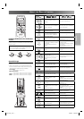
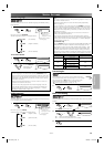
If your TV is compatible with 525 progressive scanning and you want to enjoy that high quality picture;
You must select the connection Method 3 above and progressive scanning mode. To set the mode, set “PROGRESSIVE” to “ON” in the DISPLAY
menu, so that the PROGRESSIVE indicator on the front panel lights on. See pages 16, 17 for more details.
• When “PROGRESSIVE” is “ON”, video signals from the unit’s VIDEO OUT and S-VIDEO OUT jacks will be distorted or not be output at all.
If your TV is not compatible with progressive scanning;
Use this unit in interlace mode and
set “PROGRESSIVE” to “OFF” either in the DISPLAY menu or by pressing and holding
PLAY B
on the front of the
unit for more than 5 seconds,
so that the PROGRESSIVE indicator on the front panel lights off.
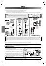
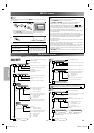
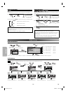
RF Modulator Connection
If your TV has Antenna input jack only, it is still possible to connect this unit to your TV by using a STEREO AUDIO/VIDEO RF Modulator
(commercially available).
In this case, follow the instructions below.
1. Connect the AUDIO/VIDEO output jacks of this unit to the AUDIO/
VIDEO input jacks of your RF Modulator by audio and video cables.
2. The antenna input jack of your TV may have been already occupied.
If so, disconnect the RF cable from your TV, and then connect the
RF cable to your RF Modulator (usually marked “ANT IN”).
3.
Connect your RF modulator to your TV by another RF cable.
4.
Set your RF modulator’s channel 3/4 switch to either 3 or 4, whichever the
TV channel is least used in your area. If your RF modulator has a Modulator/
Antenna switch, set it according to your RF modulator’s manual.
5. Turn on your TV and choose the same channel as you set the RF mod-
ulator’s channel 3/4 switch to. For more details, follow the instructions
supplied with the RF Modulator.
Hint
• The quality of picture may become poor if the unit is connected to an RF Modulator.
LC
R
/ P
R
C
B
/ P
B
Y
R
AUDIO
OUT
VIDEO
OUT
COMPONENT
VIDEO OUT
S-VIDEO
OUT
DIGITAL
AUDIO OU T
COAXIAL
E175216
TO T VCHANNEL VIDEO AUDIO
RL34
ANT INAC 120V
(Back of TV)
Video/Audio
cables
(supplied)
(Back of this unit)
RF cable
(commercially available)
Antenna
Cable
Signal
3
2
1
Antenna input jack
Stereo Audio/Video RF Modulator
(commercially available)
SETUP
CONNECTIONS
E61U1UD_1.indd 8E61U1UD_1.indd 8 8/8/2005 11:50:13 AM8/8/2005 11:50:13 AM