


26
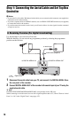
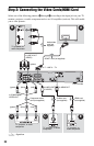
B Audio L/R (left/right) input jacks
This connection will use your TV’s or audio
component’s two speakers for sound.
z Hint
For correct speaker location, refer to the operating
instructions supplied with the connected
components.
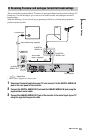
b Notes
• Do not connect your TV’s audio output jacks to
the LINE IN (R-AUDIO-L) jacks at the same
time. This will cause unwanted noise to come
from your TV’s speakers.
• With connection B, do not connect the LINE IN
(R-AUDIO-L) and LINE 2 OUT (R-AUDIO-L)
jacks to your TV’s audio output jacks at the same
time. This will cause unwanted noise to come
from your TV’s speakers.
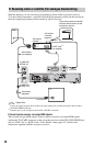
• With connection A, after you have completed
the connection, make the appropriate settings in
the “Audio Out” setup (page 133). Otherwise, no
sound or a loud noise will come from your
speakers.
• When you connect the recorder to an audio
component using an HDMI cord, you will need
to do one of the following:
– Connect the audio component to the TV with
the HDMI cord, or
– Connect the recorder to the TV with a video
cord other than HDMI cord (component video
cord, S-video cord, or audio/video cord).
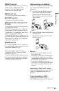
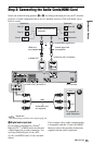
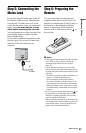
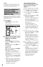
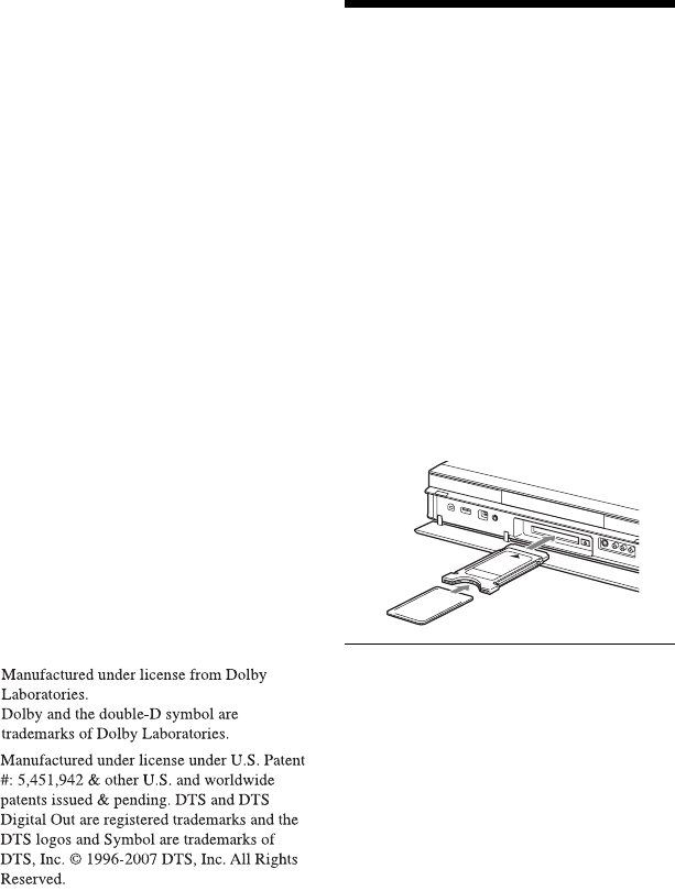
Step 4: Inserting a
Conditional Access
Module (CAM) (RDR-
HXD795/HXD895/
HXD995/HXD1095 only)
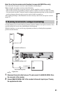
Insert a conditional access module (CAM)
provided by your service provider to receive
scrambled digital broadcasting. This
recorder is designed to work with modules
that support the DVB standard. Contact your
service provider to obtain the right kind of
CAM.
Insert the CAM into the CAM slot as far as
it will go.
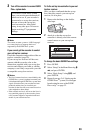
To remove the CAM
Press Z located on the right side of the CAM
slot.
b Notes
• The CAM slot accepts only Type I and Type II
PC cards. Do not insert other cards or
unacceptable objects into the CAM slot.
• Do not remove or insert the CAM while
receiving broadcasts. This will cause the picture
not to be displayed.
*1
*2