


16
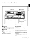
Location and Function of Parts
Chapter 1 Overview
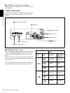
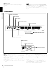
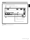
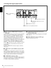
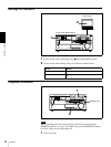
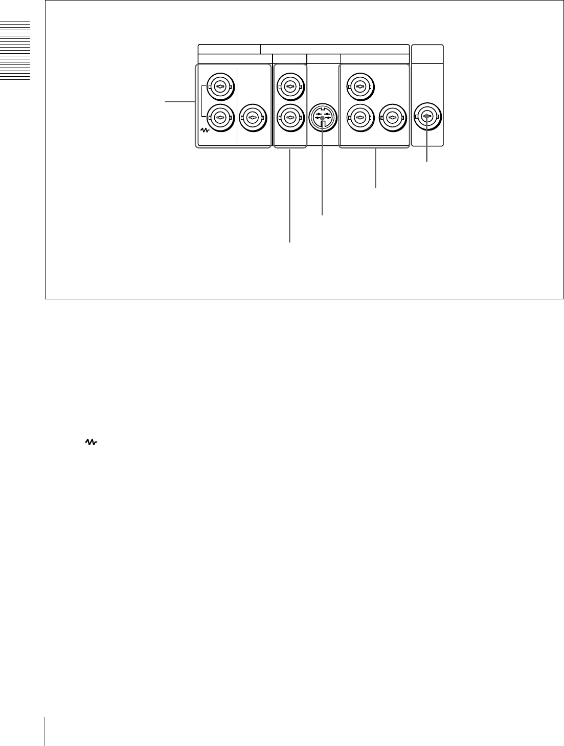
A Analog video signal output section
a REF. (reference) VIDEO IN/OUT connectors
(BNC type)
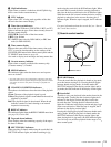
Input a reference video signal. The IN connector block has
a built-in automatic 75 Ω termination switch. When a
signal is input to the upper REF. VIDEO IN connector
with no bridging (loop-through) connection made, the
connector is terminated with an impedance of 75 Ω
automatically. To connect the reference video signal input
to the upper REF. VIDEO IN connector also to other
equipment, use the lower REF. VIDEO IN connector
(marked ). When the lower REF. VIDEO IN connector
is used, the built-in 75 Ω termination switch turns off
automatically.
The REF. VIDEO OUT connector outputs a reference
video signal.
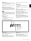
b VIDEO OUT 1 and 2 (SUPER) connectors (BNC
type)
These connectors output analog composite video signals.
When the CHARA. DISPLAY menu item (see page 40) is
set to ON (factory default setting), connector 2 (SUPER)
outputs a signal with superimposed text information.
c S VIDEO OUT connector (4-pin)
This connector outputs an S-video signal with separated Y
(luminance) and C (chroma: 3.58 MHz for DSR-1600A or
4.43 MHz for DSR-1600AP) components.
d COMPONENT VIDEO OUT Y/R−Y/B−Y
connectors (BNC type)
These connectors output analog component video signals
(Y/R−Y/B−Y).
e TIME CODE OUT connector (BNC type)
Outputs the playback time code.
TIME
CODE
VIDEO
(SUPER)
S VIDEO
COMPONENT VIDEO
ANALOG VIDEO
REF. VIDEO
IN OUT OUT OUT OUT
OUT
Y
R-Y
B-Y
1
2
e TIME CODE OUT connector
d COMPONENT VIDEO OUT Y/R−Y/B−Y
connectors
c S VIDEO OUT connector
b VIDEO OUT 1 and 2 (SUPER) connectors
a REF. VIDEO IN/OUT
connectors