


9
Location and Function of Parts
Chapter 1 Overview
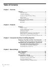
Location and Function of Parts
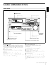
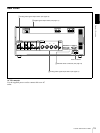
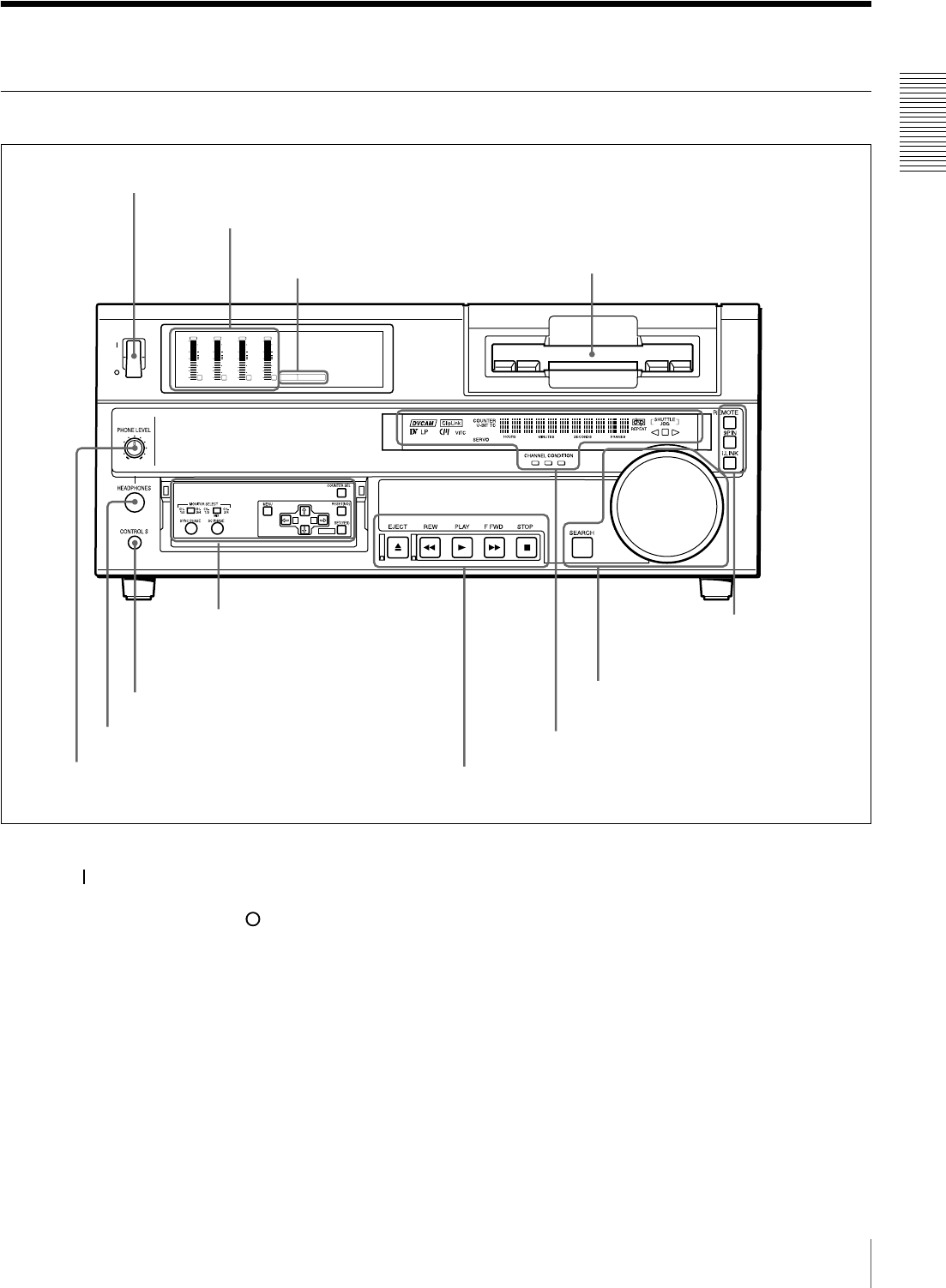
Front Panel
a POWER switch
Press the “ ” side to power the unit on. When the unit is
powered on, the display windows in the front panel lights.
To power the unit off, press the “ ” side of the switch.
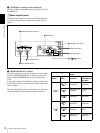
b Audio level meters
These show the audio levels of channels 1 to 4 during
playback.
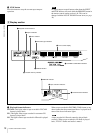
c PB FS (playback audio sampling frequency)
display
Indicates the sampling frequency (48 kHz, 44.1 kHz or 32
kHz) at which audio is recorded on tape.
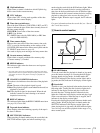
d Cassette compartment
Accepts DVCAM, DV and DVCPRO (25M)
videocassettes.
For details of usable cassettes, see page 19.
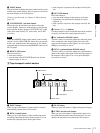
e PHONE LEVEL control knob
Controls the volume of the headphones connected to the
HEADPHONES connector.
f HEADPHONES connector (stereo phone jack)
Connect stereo headphones for headphone monitoring
during playback.
The audio signal you want to monitor can be selected with
the MONITOR SELECT switches on the menu control
panel.
dB
0
-12
-20
-30
-40
-60
dB
0
1
0
-1
-2
OVER
1
dB
0
-12
-20
-30
-40
-60
dB
0
1
0
-1
-2
OVER
2
dB
0
-12
-20
-30
-40
-60
dB
0
1
0
-1
-2
OVER
3
dB
0
-12
-20
-30
-40
-60
dB
0
1
0
-1
-2
OVER
4
PB FS
48k44.1k32k
POWER
A B
MARK
c PB FS display
a POWER switch
d Cassette compartment
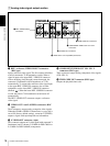
AMenu control panel (inside of
the door) (see page 10)
ERemote control
setting section
(see page 14)
DSearch control section
(see page 13)
CDisplay section (see page 12)
f HEADPHONES connector
g CONTROL S connector
BTape transport control section (see page 11)
b Audio level meters
e PHONE LEVEL control knob