


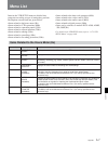
Menu List
A-8 Appendix
Appendix
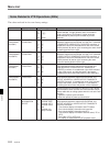
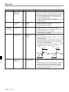
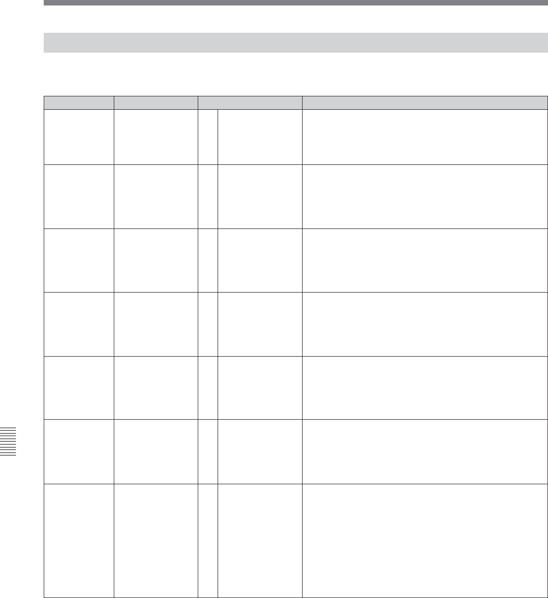
The values enclosed in a box are factory settings.
Items Related to VTR Operations (000s)
001
PREROLL TIME
00
l
[05]
l
30
Item number
Settable range
Item
Function
Selects the preroll time. A preroll time of 0 to 30 seconds
can be selected. Though generally set to 3 seconds or
longer, preroll time of 5 seconds or longer would be
recommended for phase synchronization by an edit
controller.
0 sec
l
[5sec]
l
30 sec
002
(DVW-A500/1
and 500/1)
CHARACTER
H-POSITION
Sets the horizontal screen position of the superimposed
characters output from the SERIAL V/A OUTPUT 4(SUPER)
or COMPOSITE VIDEO OUTPUT 3(SUPER) connector. A
hexadecimal value of 00 indicates the far left of the screen,
and 24 (decimal 36) the far right. Increasing the value moves
the starting position to the right.
00
l
[14]
l
24
002
(DVW-A500P/1
and 500P/1)
Sets the horizontal screen position of the superimposed
characters output from the SERIAL V/A OUTPUT 4(SUPER)
or VIDEO OUTPUT COMPOSITE 3(SUPER) connector. A
hexadecimal value of 00 indicates the far left of the screen,
and 22 (decimal 34) the far right. Increasing the value
moves the starting position to the right.
CHARACTER
H-POSITION
00
l
[12]
l
22
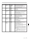
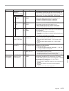
003
(DVW-A500/1
and 500/1)
CHARACTER
V-POSITION
00
l
[56]
l
6A
Sets the vertical screen position of the first line of
superimposed characters output from the SERIAL V/A
output 4(SUPER) or VIDEO OUTPUT COMPOSITE
3(SUPER) connector. A hexadecimal value of 00 indicates
the top of the screen, and 6A (decimal 87) the bottom.
Increasing the value lowers the position of the characters.
00
l
[14]
l
24
00
l
[12]
l
22
00
l
[56]
l
6A
003
(DVW-A500P/1
and 500P/1)
Sets the vertical screen position of the first line of
superimposed characters output from the SERIAL V/A
OUTPUT 4(SUPER) or VIDEO OUTPUT COMPOSITE
3(SUPER) connector. A hexadecimal value of 00 indicates
the top of the screen, and 6F (decimal 111) the bottom.
Increasing the value lowers the position of the characters.
CHARACTER
V-POSITION
00
l
[6A]
l
81
00
l
[6A]
l
81
004
Specifies phase synchronization of the two VTRs in phase
synchronization, when the units are connected with a 9-pin
remote cable with an editing system with this unit as the edit
controller.
0: Operates in phase synchronization
1: Does not operate in phase synchronization
SYNCHRONIZE
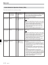
005
Determines the information to be displayed as
superimposed characters output from the SERIAL V/A
OUTPUT 4(SUPER) or VIDEO OUTPUT COMPOSITE
3(SUPER) connector.
0: Time counter display information and VTR status.
1: Time counter display information and user bits.
2: Time counter display information and CTL.
3: Time counter display information and time code (LTC or
VITC).
4: Time code (LTC or VITC) only.
5: “R” (replay) is displayed during DT playback mode.
DISPLAY
INFORMATION
SELECT
[timedatastatus]
time data & UB
time data & CTL
time data & time
data
time data only
replay indicate
[0]
1
[on]
off
&
[0]
1
2
3
4
5