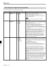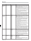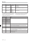
Menu List
A-38 Appendix
Appendix
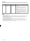
K07
(DVW-A500/1
and 500/1)
Item number Settable range
Function
CAPSTAN LOCK
[2F]
4F
Item
[0]
1
Switches the capstan servo lock mode for editing or playing
a tape with decoded component signals (i.e., a tape with
composite input data recorded on a Digital Betacam VTR
or Betacam/Betacam SP VTR).
0: The capstan servo is locked every 2 fields. Since color
framing is disabled, phase shifting (H-shifting) of output
video signals does not occur during playback. This is
the normal setting for editing or playback of component
signals.
To enhance the frequency characteristics, H-shifting of
the video output on the basis of the decoding
information on the tape may also be performed by
setting the item 712.
1: The capstan servo is locked to the color frame every 4
fields. The VTR maintains the phase of the video output
signals even after repeated stopping and restarting of
playback. Use this setting if you require continuity in
video phase at edit points during editing or playback of
composite signals, or when you perform AB rolling.
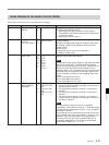
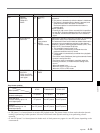
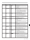
CAPSTAN LOCK
K07
(DVW-A500P/1
and 500P/1)
[2F]
4F
8F
Switches the capstan servo lock mode for editing or playing
a tape with decoded component signals (i.e., a tape with
composite input data recorded on a Digital Betacam VTR
or Betacam/Betacam SP VTR).
0: The capstan servo is locked every 2 fields. Since color
framing is disabled, phase shifting (picture shifting) of
output video signals does not occur during playback.
This is the normal setting for editing or playback of
component signals.
To enhance the frequency characteristics, H-shifting of
the video output on the basis of the decoding
information on the tape may also be performed by
setting the item 712.
1: The capstan servo is locked every 4 fields. This is the
normal setting for editing of component signals with
quick servo lock.
To enhance the frequency characteristics, H-shifting of
the video output on the basis of the decoding
information on the tape may also be performed by
setting the item 712.
2: The capstan servo is locked to the color frame every 8
fields. The VTR maintains the phase of the video output
signals even after repeated stopping and restarting of
playback. Use this setting if you require continuity in
video phase at edit points during editing or playback of
composite signals, or when you perform AB rolling.
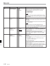
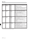
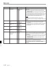
[0]
1
2
TIMER SELECT
K08
[CTL]
TC
UBIT
[0]
1
2
Selects the time data display.
0: Displays the value read by the time code reader or the
value generated by the time code generator. To switch
between VITC and LTC, press the [F5] (TC SEL) button.
1: Counts the CTL signals on the playback tape or the CTL
signals being recorded on the tape, and displays the
tape running time in hours, minutes, seconds, and
frames.
2: Displays user bits data inserted in time code being
played back, or the user bits data inserted in time code
being recording. To switch between VITC and LTC,
press the [F5] (TC SEL) button.
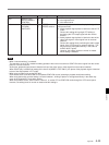
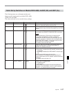
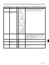
TC SELECT
K09 [ltc]
vitc
auto
[0]
1
2
Selects the time code to be read by the time code reader
during playback.
0: Reads LTC.
1: Reads VITC.
2: Reads VITC when the playback speed is ±1/2 times
normal speed or less, and LTC when it is greater than
±1/2 times normal speed.


