


11
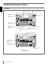
Location and Function of Parts
Chapter 1 Overview
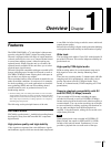
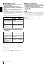
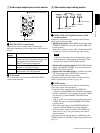
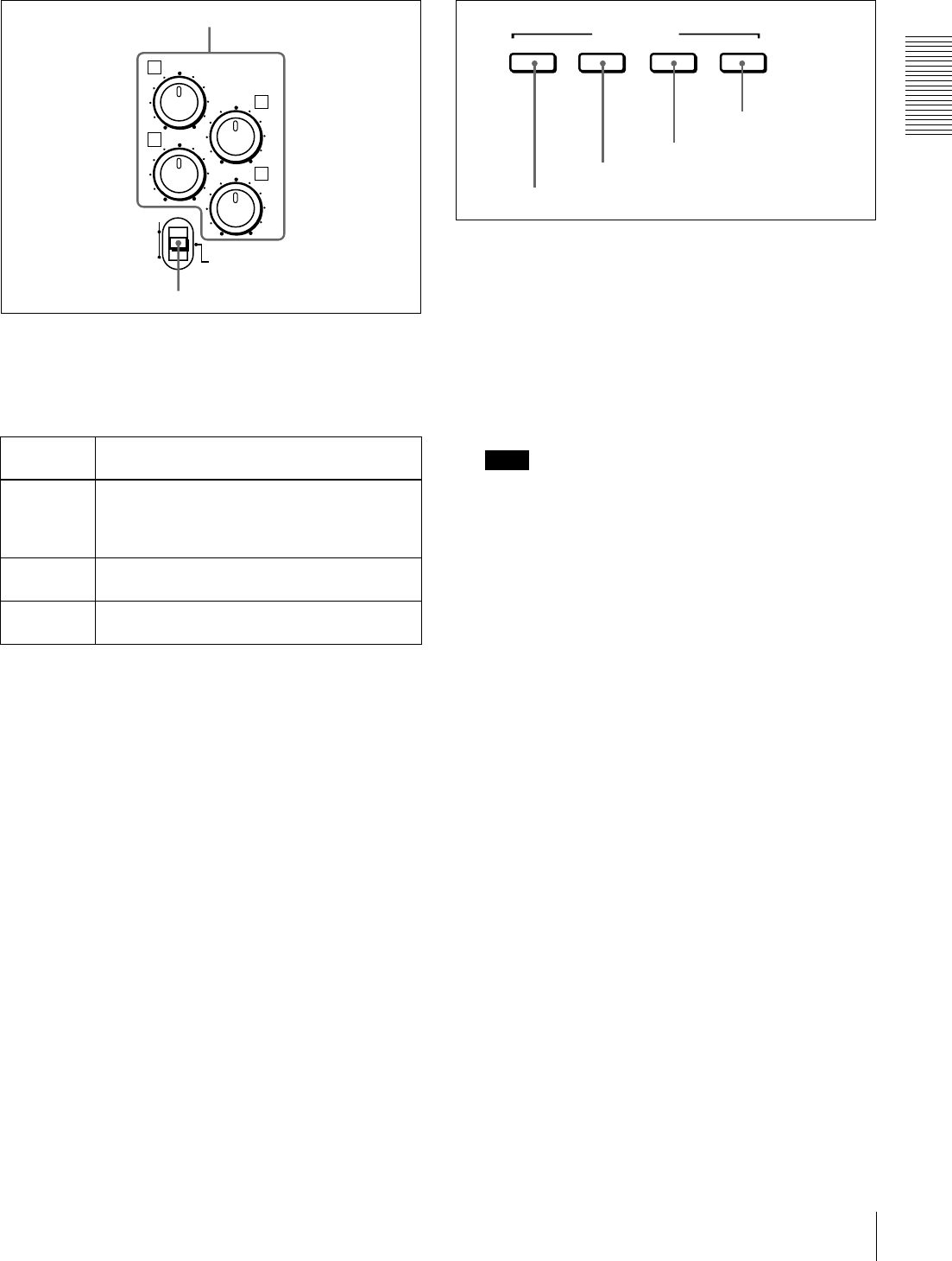
A Audio input/output level control section
a
aa
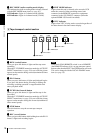
a REC/PB LEVEL control knobs
These knobs used to control audio levels function
differently depending on the setting of the VAR switch as
follows.
b
bb
b VAR switch
Use to switch the way in which the REC/PB LEVEL
control knobs function.
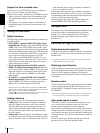
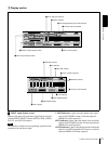
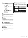
B Video/audio input setting section
a
aa
a SDTI/i.LINK (SDTI (QSDI) interface/i.LINK
selection) button
Each press of this button cycles through the following
input signal selection options.
• Digital video signal in SDTI (QSDI) format input to the
SDI/SDTI (QSDI) IN connector (optional DSBK-1501
board required)
When this is selected, use the CH1 1/2 button and CH2
3/4 button to select the required input audio signals.
Note
In this case, the phases of the selected audio signals
will be about two frames ahead of the phase of the
digital video signal in SDTI (QSDI) format.
• Digital video and audio signals in SDTI (QSDI) format
input to the SDI/SDTI (QSDI) IN connector (optional
DSBK-1501 board required)
• Digital video and audio signals in i.LINK-compatible
DV format input to the i.DV IN/OUT connector
(optional DSBK-1503 board required)
The selection made with this button is indicated in the
INPUT signal display section (see page 14).
b
bb
b VIDEO button
Each press of this button cycles through the following
input video signal selection options.
•
C
omposite video signal input to the VIDEO IN
connector (optional DSBK-1504/1504P board required)
• S-video (separated Y and C) signals input to the VIDEO
IN connectors (optional DSBK-1504/1504P board
required)
• Y, R−Y and B−Y component video signals input to the
VIDEO IN connectors (optional DSBK-1504/1504P
board required)
• SDI video signal input to the SDI/SDTI (QSDI) IN
connector (optional DSBK-1501 board required)
• Video test signal (selected with the INT VIDEO SG
menu item (see page 64)) generated by the internal
signal generator
The selection made with this button is indicated by the
VIDEO indicators in the INPUT signal display section (see
page 13).
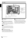
VAR switch
setting
Functions of control knobs
PRESET Control knobs are not effective.
The analog audio input/output levels are set to
the reference level set with the LEVEL
SELECT menu item
(see page 66)
.
REC Control the analog/digital audio input levels on
channels 1 to 4 during recording.
PB Control the analog/digital audio output levels
on channels 1 to 4 during playback.
REC/PB
LEVEL
PRESET
VAR
REC
PB
1
3
2
4
a REC/PB LEVEL control knobs
b VAR switch
INPUT SELECT
SDTI/i.LINK VIDEO
CH1 1/2 CH2 3/4
d CH2 3/4 button
c CH1 1/2 button
b VIDEO button
a SDTI/i.LINK button