


81
Connections for a Cut Editing System
Chapter 5 Connections and Settings
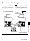
Connections for a Cut Editing System
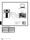
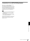
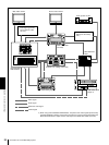
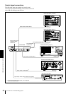
The following figure shows a cut editing system
configuration that includes two DSR-1500/1500P units to
serve as the player and recorder.
For details of connecting devices other than the DSR-
1500/1500P, refer to the instruction manual for each
device.
Notes
• This application requires both of the DSR-1500/1500P
units (recorder and player) to be fitted with the optional
DSBK-1501 board.
• The DSR-1500/1500P units shown in the following
figure are fitted with the optional DSBK-1501, DSBK-
1503, and DSBK-1504/1504P boards.
SDI/SDTI
(QSDI)
OUT
SDI/SDTI
(QSDI)
IN
MONITOR
VIDEO
OUT B-Y/CPST
(SUPER)
REMOTE
REMOTE
VIDEO OUT
Y/CPST
REF.
VIDEO IN
PLAYER
1
13
2
1
2
RECORDER
MONITOR
VIDEO
OUT B-Y/CPST
(SUPER)
13
When you select assemble or insert editing mode on the editing
control unit, the two DSR-1500/1500P units (recorder and
player) will automatically enter the selected editing mode.
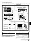
A 75 Ω coaxial cable (not supplied)
C Cable with RCA phono plugs
(not supplied)
B 9-pin remote control cable
(not supplied)
DSR-1500/1500P
(player)
DSR-1500/1500P
(recorder)
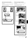
Audio input
Composite
video input
Source monitor
Main monitor
Editing control unit (RM-450/450CE,
PVE-500, etc.)
a)
Audio input
a)
For the settings on the editing control unit, see
“Settings on an editing control unit” on page 88
.
Composite
video input