


18
Location and Function of Parts
Chapter 1 Overview
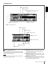
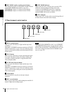
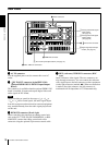
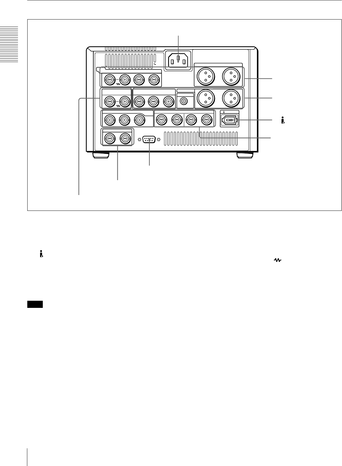
Rear Panel
a
aa
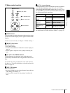
a AC IN connector
Use the supplied power cord to connect this to an AC
outlet.
b
bb
b DV IN/OUT connector (6-pin IEEE-1394)
(optional DSBK-1503 i.LINK/DV Input/Output
Board)
This connector is available when the optional DSBK-1503
board is installed. It inputs and outputs digital video and
audio signals in DV format.
Note
When searching at speeds in the range +
1
/
2
to +
1
/
30
or
−
1
/
30
to −
1
/
2
times normal speed, the audio signal output
from this connector and monitored on external equipment
may sound differently from the audio signal played back
on this unit.
c
cc
c REMOTE connector (D-sub 9-pin)
When controlling this unit from an editing control unit
such as the ES-7, PVE-500, BVE-600/800/910, or RM-
450/450CE, connect the editing control unit to this
connector using the optional 9-pin remote control cable.
d
dd
d REF. (reference) VIDEO IN connectors (BNC
type)
Input a reference video signal. The two connectors are
loop-through connectors. You can connect the reference
video signal input to the left connector to other equipment
via the right connector (marked ). When no connection
is made to the right connector, the left connector is
terminated with an impedance of 75 Ω automatically.
DV IN/OUT
REMOTE
AC IN
1/3
2/4
1/3
2/4
AUDIO IN
VIDEO
IN
Y/CPST R-Y/C B-Y
REF.VIDEO VIDEO OUT
AUDIO OUT
MONITOR
IN
IN OUT1 OUT2
Y/CPST
IN
INTC OUT
1/2 3/4 1/2 3/4
OUTAUDIO I/O (AES/EBU)
R-Y/C/CPST
(SUPER)
B-Y/CPST
SDI/SDTI
(QSDI)
a AC IN connector
b DV IN/OUT connector
A Analog video/audio signal
input section
(see page 19)
B Analog video/audio signal
output section
(see page 20)
C Digital signal input/output
section
(see page 21)
c REMOTE connector
D Time code input/output section
(see page 21)
d REF. VIDEO IN connectors