


28
Recording
Chapter 2 Recording and Playback
1
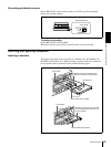
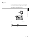
Power on the video monitor, then set its input switches according to the
signals input from this unit.
2
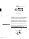
Set up the player to play back a tape.
For details, refer to the operating instructions for the player.
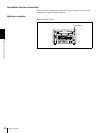
3
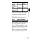
Power on this unit by pressing on the side of the POWER switch.
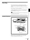
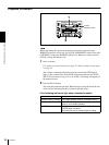
4
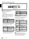
When the REMOTE indicator is off (the external editing control unit is not
used), use the COUNTER SELECT button to select the type of time data to
be used.
Each press of this button cycles through three options: COUNTER (CNT
value), TC (time code), and U-BIT (user bit data). The time data type
indicator for each option lights as it is selected.
When the REMOTE indicator is lit, selection of the time data type is carried
out at the editing control unit.
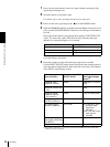
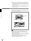
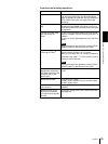
5
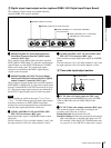
Select the formats of video and audio input signal to be recorded.
Use the INPUT SELECT buttons in the video/audio input setting section to
select the desired signal formats. Each selection is shown by a lit indicator
in the INPUT signal display section.
a) The indicators without the corresponding optional boards (DSBK-1501/1503/1504/1504P)
installed in the unit do not light.
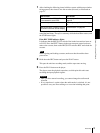
Selected time data Time data type indicator
Count value of the time counter COUNTER
Time code TC
User bit data U-BIT
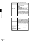
Video input signal
(input connector)
Corresponding INPUT
SELECT button
Lit indicator in the
INPUT signal display
section
a)
Composite signal
(VIDEO IN: Y/CPST)
VIDEO COMPOSITE in VIDEO
group
Separated Y/C signal
(VIDEO IN: Y/CPST and
R−Y/C)
VIDEO S VIDEO in VIDEO
group
Component signal
(VIDEO IN: Y/CPST,
R−Y/C, and B−Y)
VIDEO Y−R,B in VIDEO group
SDI signal
(SDI/SDTI (QSDI) IN)
VIDEO SDI in VIDEO group
SDTI (QSDI) signal
(SDI/SDTI (QSDI) IN)
SDTI/i.LINK SDTI: both SDTI video
and audio input
signals are
recorded.
V:SDTI: only SDTI video
input signal is
recorded.
i.LINK-compatible digital
video signal in DV format
(i.DV IN/OUT)
SDTI/i.LINK i.LINK
Internal test video signal VIDEO SG in VIDEO group