


90
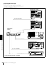
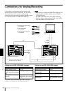
Connections for Analog Recording
Chapter 5 Connections and Settings
Connections for Analog Recording
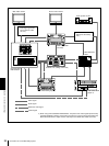
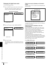
It is possible to record analog playback signals from
another recorder or player on this unit. The following
shows connections for a system in which analog
component video signals and two channels of audio signals
are recorded between two DSR-1500/1500P units.
Notes
• This application requires the DSR-1500/1500P unit used
as the recorder to be fitted with the optional DSBK-
1504/1504P board.
• The DSR-1500/1500P units shown in the following
figure are fitted with the optional DSBK-1501, DSBK-
1503, and DSBK-1504/1504P boards.
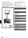
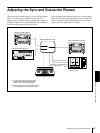
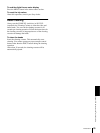
Settings on the DSR-1500/1500P (recorder)
For details of the video/audio input and audio mode
settings, see “Settings for Recording” on page 27.
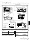
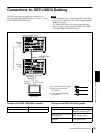
Settings on the DSR-1500/1500P (player)
2
3
3
2
1
VIDEO
OUT
B-Y/CPST
(SUPER)
MONITOR
VIDEO OUT
VIDEO IN
a)
AUDIO OUT
1/3
2/4
AUDIO IN
1/3
2/4
Video monitor
Composite
video input
Audio input
DSR-1500/1500P (player)
DSR-1500/1500P
(recorder)
B 75 Ω coaxial cable
(not supplied)
C Cable with XLR connectors
(not supplied)
A Cable with RCA phono plugs
(not supplied)
a) Three 75 Ω coaxial cables are used,
one each for Y, R−Y, and B−Y.
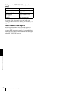
Switch/menu item Setting
LOCAL/REMOTE switch LOCAL
CH1 IN LEVEL and CH2 IN
LEVEL menu items
(see page
66)
Normally +4 dBm
REC MODE menu item
(see
page 65)
2 CHANNEL (48kHz)
(REC MODE 2CH indicator
lights.)
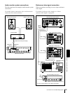
Switch/menu item Setting
LOCAL/REMOTE switch LOCAL
OUTPUT LEVEL menu items
(see page 66)
Normally +4 dBm
VIDEO OUTPUT menu item
(see page 67)
Y−R, B
(Y−R,B indicator lights.)
AUDIO OUTPUT menu item
(see page 67)
1/2 CH or 3/4 CH
(CH 1/2 or CH 3/4 indicator
lights.)