


17
Location and Function of Parts
Chapter 1 Overview
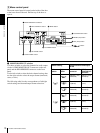
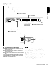
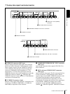
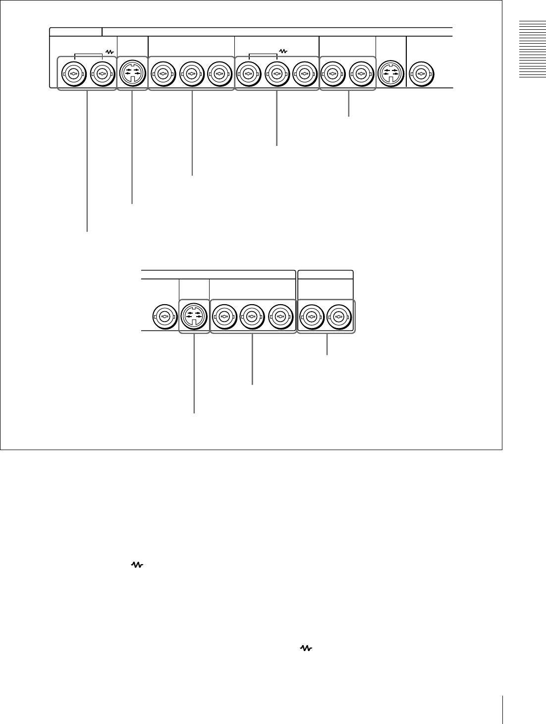
A Analog video signal input/output section
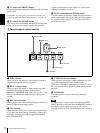
a VIDEO IN connectors (BNC type)
Input an analog composite video signal. This connector
block has a built-in automatic 75 Ω termination switch.
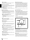
When a signal is input to the left VIDEO IN connector
with no bridging (loop-through) connection made, the
connector is terminated with an impedance of 75 Ω
automatically. To connect the signal input to the left
VIDEO IN connector also to other equipment, use the right
VIDEO IN connector (marked ). When the right
VIDEO IN connector is used, the built-in 75 Ω termination
switch turns off automatically.
b S VIDEO IN connector (4-pin)
Input an S-video signal with separated Y (luminance) and
C (chroma: 3.58 MHz for DSR-1800 or 4.43 MHz for
DSR-1800P) components to this connector.
c COMPONENT VIDEO IN Y/R−Y/B−Y connectors
(BNC type)
Input analog component video signals (Y/R−Y/B−Y) to
these connectors.
d REF. (reference) VIDEO IN/OUT connectors
(BNC type)
Input a reference video signal. The IN connector block has
a built-in automatic 75 Ω termination switch. When a
signal is input to the left REF. VIDEO IN connector with
no bridging (loop-through) connection made, the
connector is terminated with an impedance of 75 Ω
automatically. To connect the reference video signal input
to the left REF. VIDEO IN connector also to other
equipment, use the right REF. VIDEO IN connector
(marked ). When the right REF. VIDEO IN connector
VIDEO IN VIDEO OUT
S VIDEO
COMPONENT VIDEO IN REF.VIDEO
YY
R-Y
B-Y
ANALOG VIDEO
IN
S VIDEO
OUTIN 1 2
OUT
(SUPER)
VIDEO OUT
2
TIME CODE
COMPONENT VIDEO OUT
Y
R-Y
B-Y
S VIDEO
OUT IN
OUT
e VIDEO OUT 1 and 2 (SUPER)
connectors
d REF. VIDEO IN/OUT connectors
c COMPONENT VIDEO IN Y/R
−
Y/B
−
Y connectors
b S VIDEO IN connector
a VIDEO IN connectors
h TIME CODE IN/OUT connectors
g COMPONENT VIDEO OUT Y/R
−
Y/B
−
Y connectors
f S VIDEO OUT connector