


20
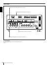
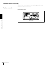
Location and Function of Parts
Chapter 1 Overview
a) Selectable on DSR-1800P only
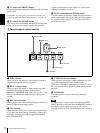
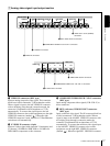
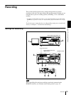
b AUDIO IN CH-1 (channel 1) to CH-4 connectors
(XLR 3-pin, female)
Use these connectors to connect separate channels of
analog audio input from a player VCR or other external
audio equipment.
You can switch the audio input level setting with the
LEVEL SELECT menu item (see page 64).
c AUDIO OUT CH-1 (channel 1) to CH-4 connectors
(XLR 3-pin, male)
These connectors output channel-1 to channel-4 analog
audio signals, respectively.
It is possible to use the AUDIO OUT CH-3 and AUDIO
OUT CH-4 connectors for audio monitor output for
channels 1 and 2, respectively (use the OUTPUT CH3/4
menu item (see page 65)).
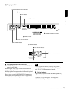
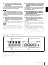
d AUDIO MONITOR OUT connector (RCA phono
jack)
This connector outputs audio signals for monitoring. The
audio signals to be output from this connector can be
selected with the MONITOR SELECT switches on the
menu control panel.
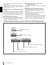
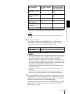
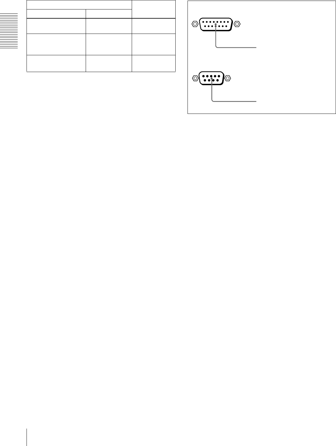
D External device connectors
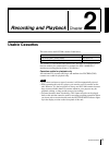
a VIDEO CONTROL connector (D-sub 15-pin)
For remote control of the internal digital video processor,
connect an optional remote control unit such as the UVR-
60/60P or BVR-50/50P to this connector.
b REMOTE connector (D-sub 9-pin)
When controlling this unit from an editing control unit
such as the ES-3, ES-7, PVE-500, BVE-600/800/910/
2000, or RM-450/450CE, connect the unit to the editing
control unit via this connector using the optional 9-pin
remote control cable.
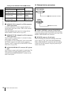
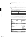
Settings of the AUDIO IN LEVEL/600 Ω
ΩΩ
Ω switches
Audio input Switch setting
Level Impedance
−
−−
−60 dBu
(microphone input)
High impedance
(about 20 kΩ)
LOW-OFF
(left position)
+4/0/−3
a)
/−
−−
−6 dBu
(line audio input)
High impedance
(about 20 kΩ)
HIGH-OFF
(middle
position)
+4/0/−3
a)
/−
−−
−6 dBm
(line audio input)
600 Ω HIGH-ON
(right position)
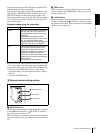
REMOTE
VIDEO CONTROL
a VIDEO CONTROL connector
b REMOTE connector