


18
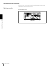
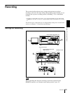
Location and Function of Parts
Chapter 1 Overview
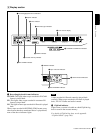
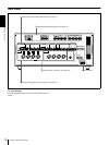
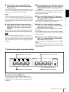
is used, the built-in 75 Ω termination switch turns off
automatically.
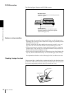
The REF. VIDEO OUT connector outputs a reference
video signal, except when i.LINK is selected in the INPUT
SELECT section (see page 11).
e VIDEO OUT 1 and 2 (SUPER) connectors (BNC
type)
These connectors output analog composite video signals.
When the CHARA. DISPLAY menu item (see page 59) is
set to ON (factory default setting), connector 2 (SUPER)
outputs a signal with superimposed text information.
f S VIDEO OUT connector (4-pin)
This connector outputs an S-video signal with separated Y
(luminance) and C (chroma: 3.58 MHz for DSR-1800 or
4.43 MHz for DSR-1800P) components.
g COMPONENT VIDEO OUT Y/R−Y/B−Y
connectors (BNC type)
These connectors output analog component video signals
(Y/R−Y/B−Y).
h TIME CODE IN/OUT connectors (BNC type)
Input SMPTE time code (for DSR-1800) or EBU time
code (for DSR-1800P) externally generated to the IN
connector.
The OUT connector outputs a time code according to the
operating state of the unit, as follows:
During playback: the playback time code
During recording: the time code generated by the internal
time code generator or the time code input to the TIME
CODE IN connector. When the EE OUT PHASE menu
item (see page 61) is set to MUTE, no time code is output.
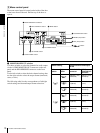
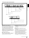
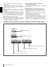
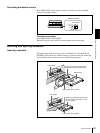
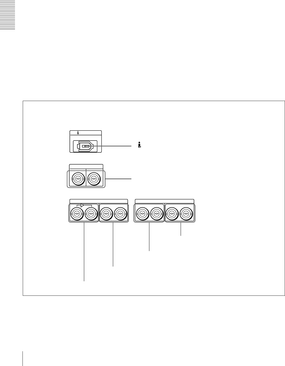
B Digital signal input/output section (optional DSBK-1801/1802/1803 boards required)
DIGITAL AUDIO(AES/EBU)
DV IN/OUT
SDTI(QSDI)
IN
CH-1/2
OUT
IN
OUT
IN
OUT
CH-1/2
CH-3/4 CH-3/4
SDI
a DV IN/OUT connector
b SDTI (QSDI) IN/OUT connectors
f DIGITAL AUDIO (AES/EBU) OUT connectors
e DIGITAL AUDIO (AES/EBU) IN connectors
d SDI OUT connectors
c SDI IN and active through output connectors