


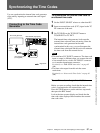

Synchronizing the Time Codes
Chapter 4 Setting the Time Code and Adjusting the Video Signals
62 (GB) Chapter 4 Setting the Time Code and Adjusting the Video Signals
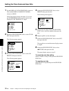
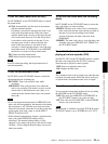
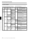
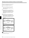
DSR-50/50P time codes
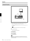
This unit has a DV IN/OUT connector. The time code
output and recorded on the tape differs as shown below
EE
INTERNAL
DV
VIDEO
S VIDEO
CAMERA
(Except DV)
UB EXT
DV
VIDEO
S VIDEO
CAMERA
(Except DV)
TC/UB IN
menu
INPUT SELECT
selector
Mode
TC IN
(EXT)
The time code output from the
TC OUT (INT) connector and the time code/
user bits recorded on the tape
Playback
Playback
Audio dubbing
Playback at various
speeds
a)
DUB1
b)
Time code on the tape
JOG TC OUT: ON – Time code on the tape;
JOG TC OUT: OFF – Mute (No output)
Duplicate
DUP1
b)
Time code of another device connected to the
DV IN/OUT connector
c)
Recording
Recording Pause
REC1
b)
Time code internally generated
c)
Recording
Recording Pause
REC1
b)
Time code internally generated
c)
Duplicate
DUP1
b)
Time code of another device connected to the
DV IN/OUT connector
c)
Recording
Recording Pause
REC1
b)
Time code internally generated
c)
Recording
Recording Pause
REC1
b)
Yes
Time code connected to TC IN (EXT) is
through-output.
No
No output from the TC OUT (INT) connector
(For details, see next page.)
: the time code
and user bits generated internally are
recorded on the tape.
TC&UB EXT
TC EXT
DV
VIDEO
S VIDEO
CAMERA
(Except DV)
Duplicate
DUP1
b)
Time code of another device connected to the
DV IN/OUT connector
c)
Recording
Recording Pause
REC1
b)
Time code: Time code of another device
connected to the DV IN/OUT
connector
User bits: User bits internally generated
d)
Yes
Time code connected to TC IN (EXT) is
through-output.
No No output from the TC OUT (INT) connector
(For details, see next page.)
: the time code
and user bits generated internally are
recorded on the tape.
Recording
Recording Pause
REC1
b)
when the INPUT SELECT selector is set to DV and
when it is set to other than DV.