


1-5
BKDW-515
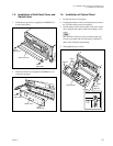
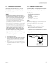
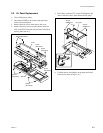
1-8. Extension of Control Panel
To extend the BKDW-515, prepare the following BKDW-
510 (Control Panel Extension Kit), AC adapter and the
connector box.
Parts Required
. 10m Extension Cable (BKDW-510)
. AC Adapter
Sony Part No.: 1-473-822-11
. Connector Box
Sony Part No.: A-8277-618-A
n
The control panel BKDW-515 can not be installed to the
control panel case BKDW-511 (sold separately).
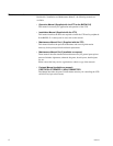
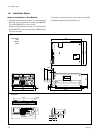
Connection
. AC100V and AC200V acceptable for AC adapter
. There is power switch on the connector box.
1. Connect the connector of the BKDW-515 to connector
of the connector box.
2. Connect the connector of an AC adapter to connector
CN3 of the connector box.
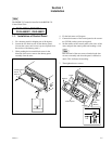
1-7. Full Reset of Control Panel
After installing the control panel in DVW-A500 and
DVW-500 (DVW-A500P and DVW-500P for PAL),
perform the full-reset operation of the control panel only
once before it is used.
m
. When the full-reset operation of the control panel is
performed, all settings of the current setup data and VTR
bank (1-8) stored on the control panel are reset to the
factory-setting value. The registration data in a PF1/2
menu is then reset to the key layout at the factory
corresponding to the VTR in which the control panel
was installed. Cue point data is also cleared.
. During installation of the control panel, the set value of
the current setup data and VTR bank can also be deliv-
ered directly. In this case, do not perform the full-reset
operation. However, if the function and option of the
VTR in which the control panel was installed differ
before and after installation, the key in a PF1/2 menu
that does not function by the VTR after installation is
deleted automatically. For the key in a PF1/2 menu that
has been deleted because it does not function by the
VTR before installation, assign it manually by the VTR
after installation as required.
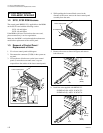
1. Turn off the power switch.
2. Turn on the power switch while pressing and holding
the [SFT], [RCL], and [SETUP] keys on the control
panel. Maintain the state in which these keys were
pressed.
3. Release the three keys after confirming that message
“CONTROL PANEL FULL RESET” is displayed on
the EL panel.
AC Adaptor
BKDW-515
Power
switch
CN4
to DVW-500/1
Rear panel
CN3
Connector box
DC9V 10m Cable
AC100/200V
1-7. Full Reset of Control Panel
1-8. Extension of Control Panel