Menu List
A-14 Appendix
Appendix
The values enclosed in a box are factory settings.
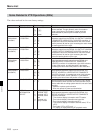
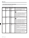
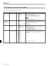
Items Related to Remote Interface (200s)
FunctionItem Settable range
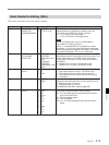
201
[0]
1
PARA RUN
Item number
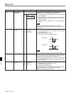
Specifies whether two or more VTRs run in parallel as
they are synchronized or not.
0: Two or more VTRs are not synchronized.
1: Two or more VTRs are synchronized.
Note
To synchronized two or more VTRs in parallel, set the
item 201 in all VTRs to “1”.
[disable]
enable
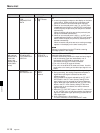
202
(DVW-A500P/1
and 500P/1only)
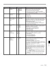
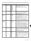
CF FLAG REPLY
[0]
1
[8F]
4F or 8F
Selects the field when the color frame lock is set to “1” in
the status data that is returned to the REMOTE1-IN (9P)
connector on the connector panel.
0: Field 8
1: Field 4 or 8
[8280]
I
82FE
8380
I
83FE
8480
I
84FE
I
I
FF80
I
FFFE
[0]
1
2
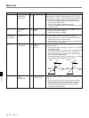
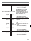
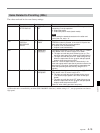
Selects the type of the communication protocol for the
REMOTE1 (9P) connector on the connector panel.
0: SONY 9 pin protocol
1: EBU-SMPTE bus protocol
2: EBU-SMPTE bus and SONY 9 pin protocols are
automatically selected.
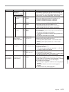
Allocates the bus for the ES BUS protocol when it is used
as the communication protocol for the REMOTE1
connector.
(Only even data are shown.)
PROTOCOL FOR
REMOTE 1
[SONY9pinprotocol]
ESBUS
AUTO selection
ES BUS ADDRESS
[8280]
I
82FE
8380
I
83FE
8480
I
84FE
I
I
FF80
I
FFFE
208
209


