


HBD-E370/E470/E570/E870/T57
88
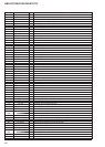
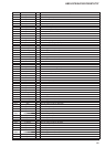
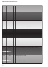
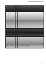
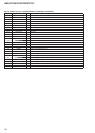
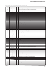
MB-134 BOARD IC1201 LAN8700C-AEZG-CTI (ETHERNET INTERFACE)
Pin No. Pin Name I/O Description
1 TX_ER I Transmit error signal input from the BD decoder
2 MDC I Serial data transfer clock signal input from the BD decoder
3 CRS O Carrier sense signal output to the BD decoder
4 MDIO I/O Two-way data bus with the BD decoder
5 nRST I Reset signal input from the system controller
6 TX_EN I Transmit enable signal input from the BD decoder
7 VDD33 - Power supply terminal (+3.3V)
8 VDD_CORE - Power supply terminal (+1.8V) Not used
9 to 12 PA0 to PA3 - Not used
13 XTAL2 O System clock output terminal (25 MHz)
14 REFCLK I System clock input terminal (25 MHz)
15 to 18 RXD3 to RXD0 O Receive data output to the BD decoder
19 RX_DV O Receive data valid signal output to the BD decoder
20 RX_CLK O Receive clock signal output to the BD decoder
21 RX_ER O Receive error signal output to the BD decoder
22 TX_CLK O Transmit clock signal output to the BD decoder
23, 24 TXD0, TXD1 I Transmit data input from the BD decoder
25 VDDIO - Power supply terminal (+3.3V)
26, 27 TXD2, TXD3 I Transmit data input from the BD decoder
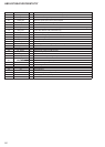
28 TXN O Serial data (negative) output to the ethernet connector
29 TXP O Serial data (positive) output to the ethernet connector
30 VDDA3.3 - Power supply terminal (+3.3V) (analog system)
31 RXN I Serial data (negative) input from the ethernet connector
32 RXP I Serial data (positive) input from the ethernet connector
33 VDDA3.3 - Power supply terminal (+3.3V) (analog system)
34 EXRES1 I Reference resistor connection terminal
35 VDDA3.3 - Power supply terminal (+3.3V) (analog system)
36 COL O Collision detect signal output to the BD decoder