Chapter 3 - Troubleshooting
CTV-68 19
Test Points
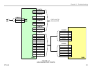
The drawing in Figure 3-7 contains the board-to-board connector and pin
information for the KDL22EX308 to identify voltages, signal and control lines
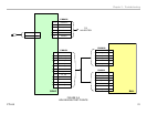
for troubleshooting purposes. Figure 3-8 illustrates the same information
for the KDL32EX308. All critical voltages and control signals are easily
accessed at the power supply board. Use this drawing in conjunction with
the previously discussed troubleshooting techniques and flowcharts for
testing operating voltages and control signals.
Circuit Board and Connector Locations
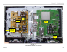
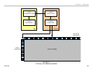
Figure 3-9 illustrates the rear of a KDL22EX308 with the cover removed.
The location of the major circuit boards and connectors for voltage checks
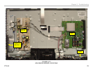
is provided. An illustration of the KDL32EX308 is shown in Figure 3-10


