Chapter 2 - Overall Circuit Description
CTV-68 4
Power Supply
KDL22EX308
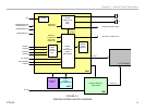
The KDL22EX308 utilizes the GD1 power supply board. There are 3
distinct sections on the power supply:
Standby Supply: Continuously operational as long as AC power is
applied, the standby supply generates 3.3VDC for the circuits requiring
power while the unit is turned off. An unregulated 15-volt line is present to
provide power to the main relay, PFC and main power supply at turn-on.
Main Supply: Once the power supply receives a power-on command
from the CPU on the BAL board, the main switching supply is turned on to
provide a regulated 12V source, along with a dedicated un-regulated 15V
for the audio circuits.
Inverter: The high voltage for the fluorescent backlights is generated by this
circuit. Out-of-phase AC voltage of approximately 1000VRMS is applied
to the balancer circuit. If the inverter circuit fails to start, for whatever
reason, the unit will shut down with a 6-blink error code displayed by the
timer LED.
KDL32EX308
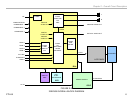
Referring to Figure 2-2 the KDL32EX308 utilizes the G2LE power supply
board. All of the other circuits are the same as the KDL22EX308 except
for the following circuits:
There are 2 distinct sections on the power supply:
Standby Supply: Continuously operational as long as AC power is
applied, the standby supply generates 3.3VDC for the circuits requiring
power while the unit is turned off. An unregulated 15-volt line is present to
provide power to the main relay, PFC and main power supply at turn-on.
Main Supply: Once the power supply receives a power-on command
from the CPU on the BAL board, the main switching supply is turned on
to provide a regulated 12V source, a dedicated un-regulated 15V for the
audio circuits and an unregulated 24V source for the inverter circuit.
Inverter
The inverter receives the unreg24V from the G2LE board and generates
the required high voltage AC to power the backlight lamps. As of the
writing of this manual, the inverter is not available as a replacement part.
The LCD panel assembly must be replaced.
Switch Unit
This board contains the power, channel and volume up/down and menu
buttons.
HLR Board
The power, standby and timer LED’s are located on this board along
with the IR remote receiver and ambient room light sensor for controlling
backlight and RGB levels.


