Chapter 4 - Appendix
CTV-68 25
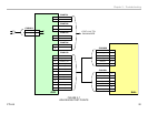
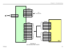
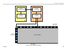
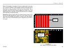
Figure 4-1 illustrates a typical LCD panel and the associated video
processing circuits as found in the WAX3 chassis. The various formats
and resolutions of video signals are processed on the BU1 board. All video
signals exit the video processor in the native resolution of the LCD panel.
In this design, the resolution is for a 1366 by 768 at 60HZ refresh rate
panel. 48 horizontal lines are discarded to match up to the 720p resolution
of the ATSC specifications so the video will exit as 720p.
The LCD panel used in this model processes 8-bit RGB video data. Before
the video information can be sent to the TCON board it must be converted
to a format that allows for practical and noise-free transmission. The large
number of parallel lines to transmit the 8-bit RGB data would need to be
sent on differential lines for noise reduction. This would require 48 lines
just for the video. The TCON circuit also requires B+, ground connections,
a communications bus, sync, and a clocking line transmitted differentially
so we can see that up to 60 lines would be required for an 8-bit video
signal and significantly more lines for a 10-bit processor. The practical
way to transmit this information is to convert the parallel video data to
a serial stream and this is accomplished by the Low-Voltage Differential
Signaling (LVDS) transmitter.
The LVDS transmitter contains a circuit to serialize the parallel data. The
parallel video information along with sync and clocking data are transmitted
via twisted line pairs. Depending on the logic level, current is sent along
one or the other of the twisted pair of wires. The receiving end of the wires
is loaded with a resistor (usually around 100 to 120 ohms). The receiver
detects the polarity of the voltage drop across the resistor to determine
the logic level. The current level swings in the wire are about 3ma with a
voltage differential of around 350mv. This allows for transmission of the
video signal with minimal EMI.
The LVDS receiver on the TCON board converts the serialized data back
to parallel. This data is processed by the timing control IC to allocate
the RGB data into serial streams for processing by the LCD panel. The
TCON transmits the pixel control data to the panel via flat, flexible circuit
board cables which can number 2 or 4 depending on the bit rate and
refresh timing of the panel. A 1366 X 768 panel requires about 180 lines
to transmit control information and B+ from the TCON. This number of
control lines is not even close to the number of horizontal or vertical rows
of pixels so the LCD panel must use this information to further expand the
ability to turn on each individual crystal. The process will be explained in
the gate and source driver paragraphs.
All of this is accomplished by the TCON board. The term “TCON” is short
for Timing Control. Other LCD panel manufacturers may have a different
name for this particular circuit but the term used by Sony will always be
TCON.


