CTV-68 3
Chapter 2 – Overall Circuit Descriptions
Overview
The primary circuits contained in the AZ1L chassis consists of a main
circuit board (designated as the BAL board), power supply (GD1 Or
G2LE) which varies based on the size of the LCD display, and the LCD
panel assembly. The TCON circuit (normally mounted external to the
LCD panel) is contained inside the panel assembly. The remaining small
boards contain switches, sensors and LED’s.
Overall Circuit Description
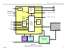
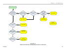
Figure 2-1 illustrates an overall block diagram of the KDL22EX308.
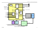
Figure 2-2 illustrates an overall block diagram for the KDL32EX308. Both
chassis designs share most of the same circuits with the power supply
and high voltage circuits to supply the lamp voltages being the significant
difference. Below is a description of the components and their function for
the KDL22EX308.
BAL Board
Common to all models utilizing the AZ1L chassis, the BAL board contains
most of the video processing circuitry along with all audio processing.
Control of the television is accomplished via CPU IC5000. Below is a list
of the key components located on the BAL board.
A/V Decoder IC9000
This IC performs several functions including the following:
Tuner: The tuner is a combination ATSC/NTSC unit. It can receive
traditional analog NTSC signals via cable or terrestrial along with ATSC
digital signals via terrestrial (8VSB) or cable (64 or 256 QAM).
Analog Video Input Switch: The analog video is A/D converted and
scaled (if necessary) to a 1920 X 1080p 60HZ resolution.
Digital Audio and Video Decoder: The MPEG2 and Digital Dolby audio
streams are received from the tuner for decompression. All video sources
which are not native 1280 X 720p 60HZ are scaled to this resolution. Digital
audio content is output to IC4200 for processing and amplification.
Audio Processing
IC4200 selects and processes all audio sources. The audio content is
processed digitally, amplified and sent to the speakers.
HDMI Switch
IC2000 functions as a switch for the 4 HDMI inputs. It also serves as
an equalizer to match the low impedance of the input jacks to the high
impedance of the input to IC9000. IC2000 also contains a shared memory
for the EDID information for each HDMI input. When a particular HDMI
input is selected, IC9000 loads the proper EDID information into the
shared memory.
CPU
IC5000 controls most of the operation of the television. All user inputs
are processed here. IC5000 also monitors key voltages and protection
circuits to shut the unit down if a problem is detected.
LVDS Transmitter
Integrated into IC9000 is a Low Voltage Differential Signaling (LVDS)
transmitter. This circuit converts the 8-bit parallel RGB video information
into a set of high speed serial lines for noise-free transmission to the
TCON board.


