Chapter 4 - Appendix
CTV-68 27
Gate Drivers
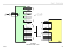
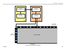
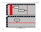
Referring to Figure 4-1, note the IC’s located along the side of the panel.
These IC’s are mounted on a flexible cable(s) which are bonded to the
LCD panel. Their function is to activate each row of pixels one at a time
starting with the first line at the top. As each line is activated, the source
drivers turn on the appropriate liquid crystals for the frame of video about
to be displayed. This continues from top to bottom until the entire frame of
video is displayed. The process is repeated for the next frame. This rate
can vary from 60 times per second or be increased to 120 or 240 as found
in the high-frame-rate panels.
Source Drivers
These IC’s provide the control voltages to turn on each RGB segment
of the vertical rows of pixels. In this example, the panel has a horizontal
resolution of 1366 pixels. Each pixel is made up of a red, green and blue
liquid crystal which means there are 4,098 columns to control.
The source drive IC’s contain shift registers along with buffer switches.
Shift registers are used to convert serial data to parallel. By using this
method, the TCON is able to transmit control information to each of the
source drivers using serial data lines. If the TCON is transmitting 8-bit
data to the panel, each data line is capable of controlling 256 lines exiting
the source drivers. Understanding how the gate and source drivers work
together makes it easier to observe a problem on the screen and determine
if the failure is panel or TCON related.
Diagnosing a Failed TCON
In order for this concept to move forward successfully, it is important that
the service industry be able to properly identify the symptoms of TCON
issues to avoid unnecessary service calls and repair costs. Accurate
analysis of TCON failures will reduce costs significantly (both in parts
costs and time) when warranty repairs are involved and will reduce the
number of COD repairs that are lost.
A good approach when determining a TCON failure is a good understanding
of which symptoms ARE NOT caused by the TCON. Examples are as
follows:
Video Process Failures: All video inputs received by the video process
circuits are handled on a frame-by-frame basis. The video frames
are converted and scaled to 8 or 10-bit RGB information. It is virtually
impossible for the video process circuits to cause a problem on a specific
area of the screen. Failures on this board usually appear as distortions,
color level shifts, video level shifts, noise that involves the entire picture,
or no picture at all. The TCON can generate symptoms that appear to be
video process related but the video process circuits cannot produce the
symptoms of a failed TCON circuit.
LVDS Cable Failures: Although problems with the LVDS cable or
connectors can generate symptoms of TCON failures this usually tends
to be intermittent and wiggling of the connectors will usually provoke
a change in the symptom on the screen. LVDS cables and connectors
have become rather robust over the past few years and most problems
are caused by technicians who damage them and this is generally quite
obvious upon close examination.
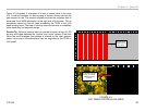
LCD Panel Failures: Some LCD panel failures could possibly be mistaken
for TCON issues. Other than damage to the LCD glass, most panel failures
are isolated to a particular area of the screen. Since the TCON disperses
the pixel data to groups of line and column drive IC’s situated on the outer
edges of the panel, it is unlikely that more than one of these IC’s would
fail at the same time. Multiple columns of stuck on or stuck off pixels
are, therefore, more likely to be the fault of the TCON circuits. The same
applies to a single row of lit or unlit pixels. The TCON simply cannot cut out
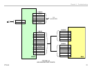
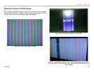
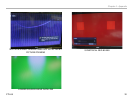
a single line of information. Figure 4-2 illustrates some typical symptoms
of failures that are caused by the LCD panel.


