


— 10 —
KV-32S40/32S45/34SL40/34SL40C/34SL40T/34SL45/35S40/35S45/37SL45/
32V40/32V65/34VL65/34VL65C/35V65/37VL65/37VL65C
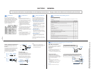
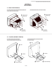
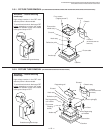
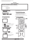
2-4. CONTROL SWITCH REMOVAL
(KV-32V65/34VL65/34VL65C/35VL65/35VL65C/37VL65C)
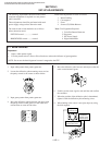
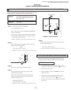
2-3. SERVICE POSITION
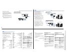
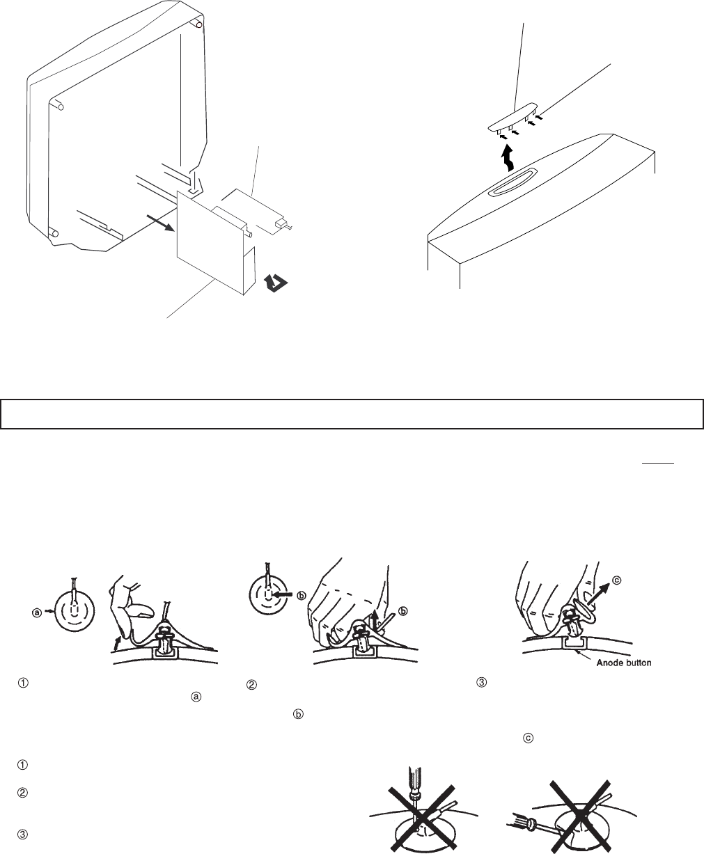
Do not use sharp objects which may cause damage to the sur-
face of the anode-cap.
Do not squeeze the rubber covering too hard to avoid damag-
ing the anode-cap. A material fitting called a shatter-hook ter-
minal is built into the rubber.
Do not force turn the foot of the rubber cover. This may cause
the shatter-hook terminal to protrude and damage the rubber.
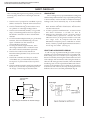
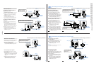
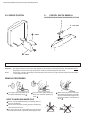
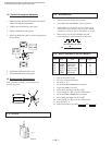
HOW TO HANDLE AN ANODE-CAP
Turn up one side of the rubber cap in
the direction indicated by arrow .
When one side of the rubber cap sepa-
rates from the anode button, the anode-
cap can be removed by turning the rub-
ber cap and pulling it in the direction of
arrow .
Use your thumb to pull the rubber cap
firmly in the direction indicated by
arrow .
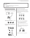
ANODE-CAP REMOVAL
WARNING:
High voltage remains in the CRT even after the power is disconnected. To avoid electrical shock, discharge CRT before
attempting to remove the anode cap. Short between anode and coated earth ground strap of CRT.
NOTE: After removing the anode, short circuit the anode of the picture tube and the anode cap to either the metal chassis, CRT shield
or carbon painted on the CRT.
REMOVAL PROCEDURES
2 2
2 2
2 G Board
1 1
1 1
1 Control Switch
2 2
2 2
2 Four Claws
1 1
1 1
1 A Board