


— 15 —
+
-
dejital
multimeter
+
-
A
ammeter
3mA dc ran
ge
+
-
dc power supply
11
R530
R531
T503
FBT
TP85
1T40
T503
FBT
TP85
R531
R530
DC Power Supply
digital multimeter
ammeter
3mA DC range
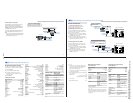
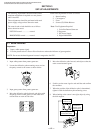
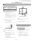
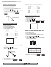
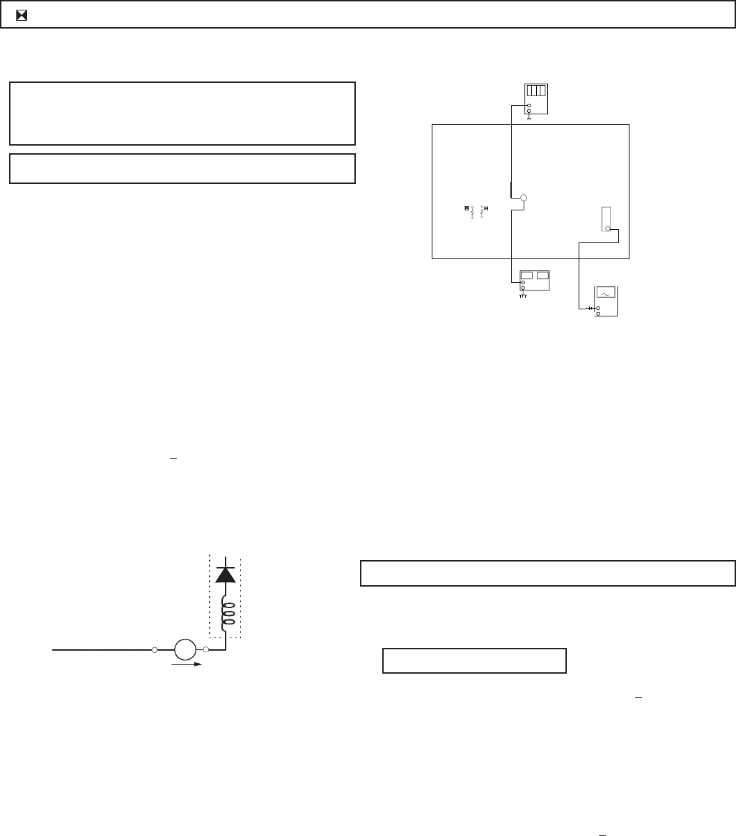
A BOARD: IC351, IC501, D519, D520, D521, C531,
C532, R387, R529, R530, R531, R532,
R533, R550, T503
G BOARD: IC643, R661
Step 1 Preparation before Confirmation
Turn the POWER switch ON.
Input a white signal and set the PICTURE and BRIGHT
controls to maximum.
Confirm that the voltage at the check terminal of TP85 is
more than 18.0 V DC when the set is operating normally.
At AC input: 120.0 ± 2.0 VAC
or220.0 ± 2.0 VAC (for 34SL40C/34VL65C/37VL65C only)
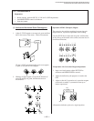
Step 2
Input a white signal and verify that I ABL is within the
specified range:
2160 + 100 µA.
At AC input: 120.0 ± 2.0 VAC
or 220.0 ± 2.0 VAC (for 34SL40C/34VL65C/37VL65C only)
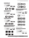
+
I ABL
ABL
T504
FBT
range
-
ammeter
3.0 mA DC
A
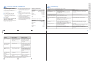
Step 3
Record the voltage between TP85 and ground.
Step 4
Using an external DC power supply, apply voltage
between TP85 and ground.
Increase the voltage gradually and confirm that the
holdown works (raster disappears) at lower than the
voltage recorded in Step 3.
Lower than 22.05 V DC
At AC input: 120.0 ± 2.0 VAC
or 220.0 ± 2.0 VAC (for 34SL40C/34VL65C/37VL65C only)
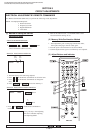
SECTION 4
SAFETY RELATED ADJUSTMENTS
Always perform the following adjustments when replacing the
following components marked with ] on the schematic diagram:
G BOARD: IC643, R661
1) Using Variac, apply AC input voltage: 130
+ 2.0 VAC
(or 220.0 ± 2.0 VAC
for 34SL40C/34VL65C/37VL65C only)
2) Input a monoscope signal.
3) Set the PICTURE control and the BRIGHT control to
initial reset value.
4) Confirm the voltage of G BOARD CN641 between
pin 1 to ground is less than 135.5
+ 1.0 V DC.
5) If step 4 is not satisfied, replace the R661and repeat the
above steps.
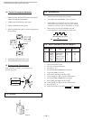
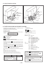
B+ VOLTAGE CONFIRMATION AND ADJUSTMENT
R530, R531 CONFIRMATION METHOD (HOLD-DOWN CONFIRMATION) AND READJUSTMENTS
A BOARD - CONDUCTOR SIDE
Step 5
Confirm that a voltage of more than 18.0 V DC appears
between TP85 and ground.
At AC input: 120.0 ± 2.0 VAC
or 220.0 ± 2.0 VAC (for 34SL40C/34VL65C/37VL65C only)
Always perform the following adjustments when replacing the following
components marked with a ] mark on the schematic diagram:
KV-32S40/32S45/34SL40/34SL40C/34SL40T/34SL45/35S40/35S45/37SL45/
32V40/32V65/34VL65/34VL65C/35V65/37VL65/37VL65C