


— 14 —
KV-32S40/32S45/34SL40/34SL40C/34SL40T/34SL45/35S40/35S45/37SL45/
32V40/32V65/34VL65/34VL65C/35V65/37VL65/37VL65C
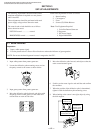
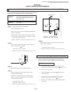
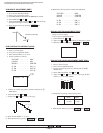
3-4. SCREEN (G2)
1. Input dot pattern from the pattern generator.
2. Set the PICTURE and BRIGHT controls at normal.
3. Adjust S BRT, G CUT, B CUT in service mode with an
oscilloscope so that voltages on the red, green, and blue
cathodes are 170Vdc for 35"/37" and 180Vdc for 32"/34".
4. Observe the screen and adjust SCREEN (G2) VR
to obtain the faintly visible background of dot signal.
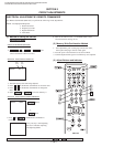
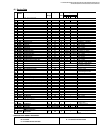
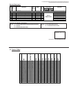
3-5. WHITE BALANCE ADJUSTMENTS
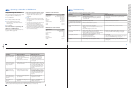
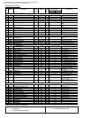
NO. Disp. Item Avg/32" Avg/35"
16 GDRV Green Drive 33 45
17 BDRV Blue Drive 33 45
18 GCUT Green Cut-off 3 6
19 BCUT Blue Cut-off 2 6
23 SBRT Sub Bright 14 10
1. Input an entire white signal.
2. Set to Service adjustment Mode.
3. Set DCOL to "0"
4. Set the PICTURE and BRIGHT to minimum.
5. Adjust with SBRT if necessary.
6. Select GCUT and BCUT with 1 and 4 .
7. Adjust with 3 and 6 for the best white balance.
8. Set the PICTURE and BRIGHT to maximum.
9. Select GDRV and BDRV with 1 and 4 .
10. Adjust with 3 and 6 for the best white balance.
11. Reset DCOL to "1".
12. Write into the memory by pressing
then **.
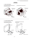
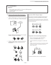
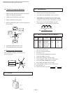
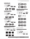
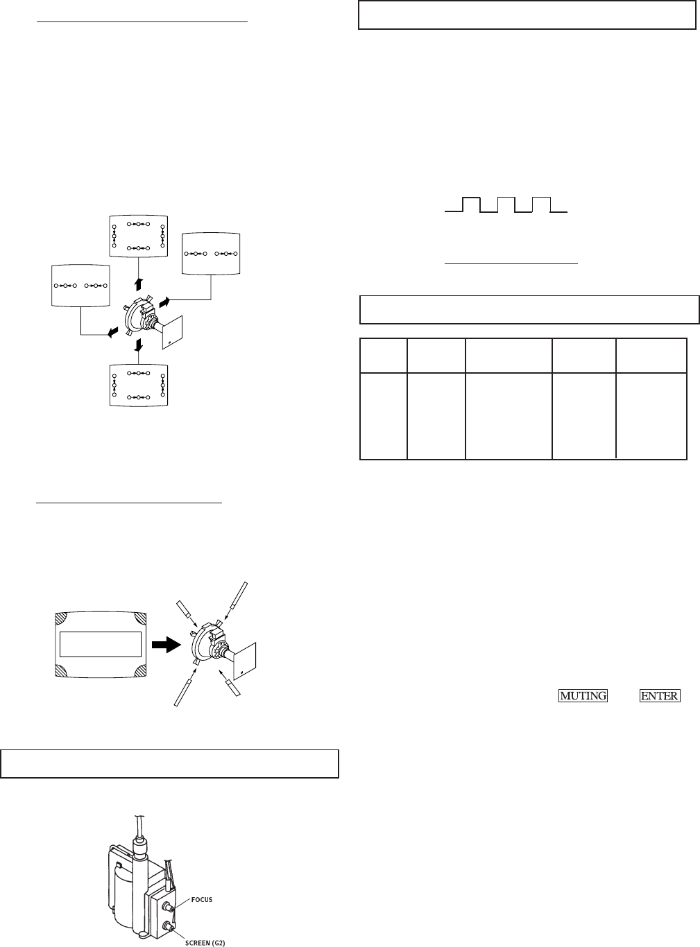
( 2 ) Dynamic Convergence Adjustment
• Before starting, perform Horizontal and Vertical
Static Convergence Adjustment.
1. Slightly loosen deflection yoke screw.
2. Remove deflection yoke spacers.
3. Move the deflection yoke for best convergence as
shown below:
BGR
B
G
R
B
G
R
RGB RGB
RGB
RGB
BGR
RGB
R
G
B
R
G
B
BGR
4. Tighten the deflection yoke screw.
5. Install the deflection yoke spacers.
(3) Screen-corner Convergence
Affix a permalloy assembly corresponding to the
misconverged areas:
ab
cd
b
a
d
c
a-d : screen-corner
misconvergence
3-3. FOCUS
Adjust FOCUS control for best picture.
NN
NN
N
NN
NN
N
pedestal
NN
NN
N
GND
170Vdc
170 V dc/ 180 V dc