


— 6 —
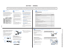
KV-32S40/32S45/34SL40/34SL40C/34SL40T/34SL45/35S40/35S45/37SL45/
32V40/32V65/34VL65/34VL65C/35V65/37VL65/37VL65C
7
AUDIO R AUDIO L VIDEO
S VIDEO
LINE
OUT
OUT
IN
OUT
IN
AUDIO OUT
(
VAR/FIX
)
VIDEO
IN
12
VHF/UHF
S VIDEO
VIDEO
L
R
AUDIO
(
MONO
)
L
R
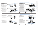
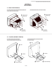
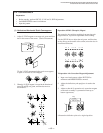
Disconnect all power sources before making any connections.
VCR must be connected and
turned on to operate PIP
(KV-32S45, 35S45 only).
VCR Connections
Connecting an antenna/cable TV
system with a VCR
1 Attach the coaxial connector from your cable
or antenna to IN on your VCR.
2 Using A/V connectors, connect AUDIO and
VIDEO OUT on your VCR to AUDIO and
VIDEO IN on your TV.*
3 Using a coaxial connector, connect OUT on
your VCR to VHF/UHF on your TV.
* If you are connecting a monaural VCR, connect only the
single white audio output to the left input on your TV.
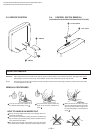
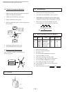
Connecting a VCR and TV with a
cable box
You will need a splitter (not supplied) for the
following connection.
1 Connect the single (input) jack of the splitter
to your incoming cable connection. Connect
the other two (output) jacks (using coaxial
cable) to IN on your cable box and VHF/UHF
on your TV.
2 Using a coaxial connector, connect OUT on
your cable box to IN on your VCR.
3 Using A/V connectors, connect AUDIO and
VIDEO OUT on your VCR to AUDIO and
VIDEO IN on your TV.
Coaxial cable
(Rear of TV)
VMC-810S/820S (not supplied)
Cable
VCR
3
1
2
AUDIO-R (red)
AUDIO-L (white)
VIDEO (yellow)
VMC-810S/820S (not supplied)
Cable box
Splitter
(not supplied)
3
AUDIO-R (red)
AUDIO-L (white)
VIDEO (yellow)
VCR
Cable
Coaxial cable
2
1
For optimum picture quality, use S VIDEO instead of
the yellow A/V cable. S Video does not provide sound,
your audio connectors must still be connected.
(Rear of TV)
AUDIO OUT
(
VAR/FIX
)
VIDEO
IN
12
VHF/UHF
S VIDEO
VIDEO
L
R
AUDIO
(
MONO
)
AUDIO R AUDIO L VIDEO
S VIDEO
LINE
OUT
OUT
IN
L
R
8
AUDIO R AUDIO L VIDEO
AUDIO R AUDIO L VIDEO
SATELLITE IN
VHF/UHF
S VIDEO
OUT
IN
LINE OUT
LINE IN
VHF/UHF
S VIDEO
OUT
IN
LINE OUT
AUDIO OUT
(
VAR/FIX
)
VIDEO
IN
12
VHF/UHF
S VIDEO
VIDEO
L
R
AUDIO
(
MONO
)
L
R
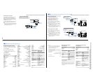
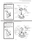
Disconnect all power sources before making any connections.
DBS receiver
Satellite
antenna
cable
VMC-810S/820S (not supplied)
1
3
2
AUDIO-R (red)
AUDIO-L (white)
VIDEO (yellow)
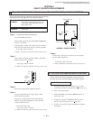
Connecting and Installing the TV (continued)
For optimum picture quality, use S VIDEO
instead of the yellow A/V cable. S Video does
not provide sound, your audio connectors
must still be connected.
DBS Connections
Connecting a DBS (Direct
Broadcast Satellite) receiver
1 Connect the cable from your satellite
antenna to your DBS receiver.
2 Attach the coaxial connector from your
cable or antenna to VHF/UHF on your TV.
3 Using A/V connectors, connect AUDIO
and VIDEO OUT on your DBS receiver to
AUDIO and VIDEO IN on your TV.
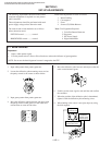
Connecting a DBS (Direct Broadcast
Satellite) receiver and a VCR
1 Connect the cable from your satellite
antenna to your DBS receiver.
2 Attach the coaxial connector from your
cable or antenna to VHF/UHF IN on your
VCR.
3 Using a coaxial connector, connect
VHF/UHF OUT on your VCR to
VHF/UHF on your TV.
4 Using A/V connectors, connect AUDIO
and VIDEO OUT on your DBS receiver to
AUDIO and VIDEO IN on your VCR.
5 Using A/V connectors, connect AUDIO
and VIDEO OUT on your VCR to AUDIO
and VIDEO IN on your TV.
(Rear of TV)
AUDIO-R (red)
AUDIO-L (white)
VIDEO (yellow)
1
2
3
VMC-810S/820S (not supplied)
VMC-810S/820S (not supplied)
4
5
(Rear of TV)
DBS receiver
VCR
Pressing TV/VIDEO on the remote
control will allow you to view from
the DBS or VCR.
VHF/UHF
S VIDEO
OUT
IN
LINE OUT
SATELLITE IN
AUDIO R AUDIO L VIDEO
AUDIO OUT
(
VAR/FIX
)
VIDEO
IN
12
VHF/UHF
S VIDEO
VIDEO
L
R
AUDIO
(
MONO
)
L
R
Cable/Antenna
Cable/Antenna
9
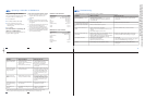
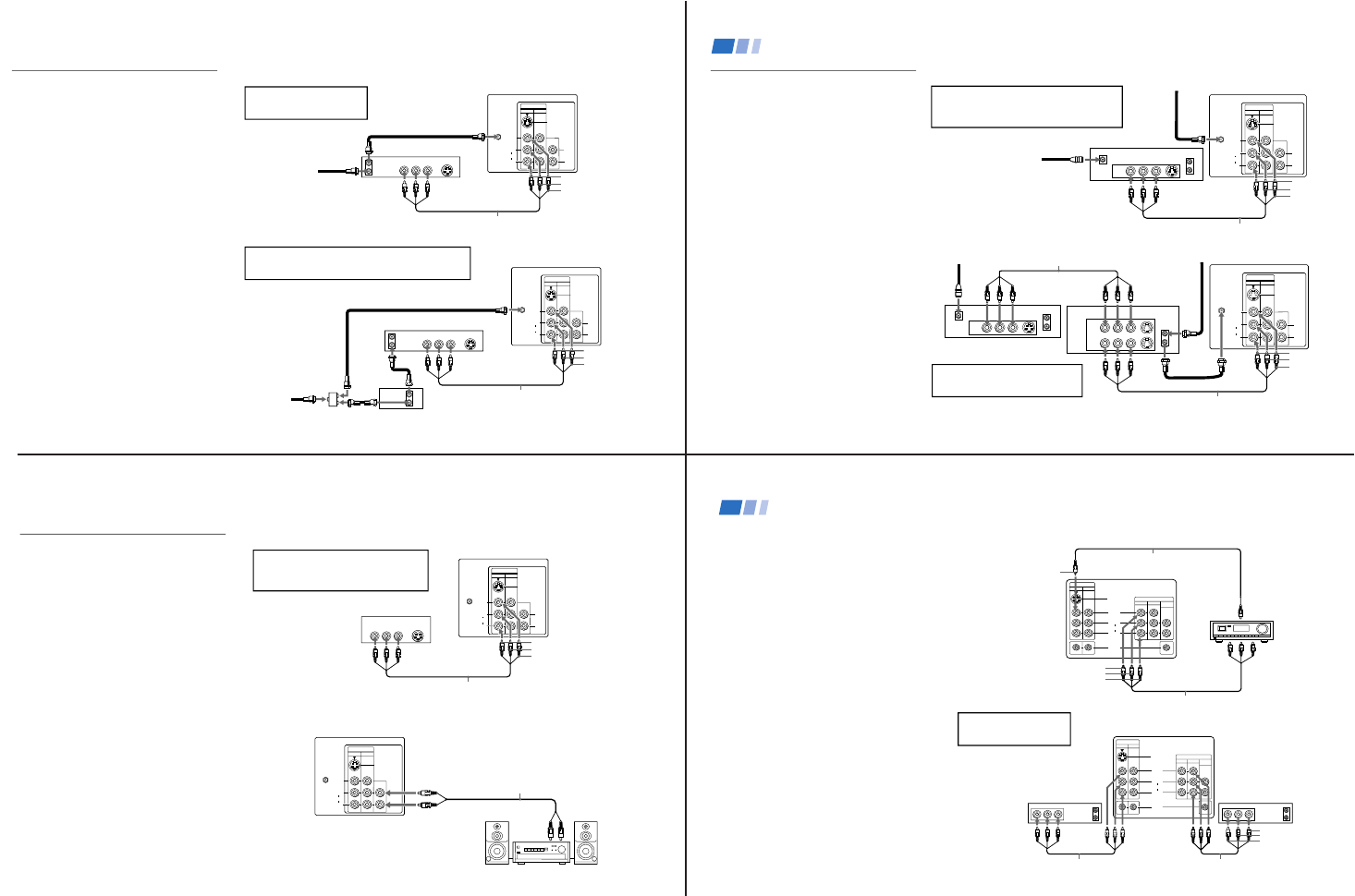
Additional Connections
The following connections are for accessories
that will enhance your viewing options.
Connecting a DVD Player
1 Using A/V connectors, connect LINE OUT
on your DVD to VIDEO IN on your TV.
Connecting an audio system
For enhanced sound, connect your audio
system to your TV.
1 Using AUDIO connectors, connect AUDIO
OUT on your TV to one of the unused line
inputs (e.g. TV, AUX, TAPE 2) on your
stereo.
2 Set your stereo to the chosen line input.
Refer to page 24 of this manual for
additional audio setup instructions.
VMC-810S/820S (not supplied)
1
(Rear of DVD player)
AUDIO-R (red)
AUDIO-L (white)
VIDEO (yellow)
Line
input
AUDIO-R (red)
AUDIO-L (white)
RK-74A
(not supplied)
1
2
Disconnect all power sources before making any connections.
For optimum picture quality, use S VIDEO
instead of the yellow A/V cable. S Video
does not provide sound, your audio
connectors must still be connected.
(Rear of TV)
(Rear of TV)
AUDIO OUT
(
VAR/FIX
)
VIDEO
IN
12
VHF/UHF
S VIDEO
VIDEO
L
R
AUDIO
(
MONO
)
HRD
AUDIO R AUDIO L VIDEO
S VIDEO
LINE OUT
AUDIO OUT
(
VAR/FIX
)
VIDEO
IN
12
VHF/UHF
S VIDEO
VIDEO
L
R
AUDIO
(
MONO
)
L
R
10
HRD
L
R
AUDIO
(
MONO
)
S VIDEO
VIDEO
IN
VIDEO 1
VIDEO 3
TV MONITOR
AUDIO
(VAR/FIX)
OUT
S-LINK
L
R
AUDIO
(
MONO
)
S VIDEO
VIDEO
IN
VIDEO 1
VIDEO 3
TV MONITOR
AUDIO
(VAR/FIX)
OUT
S-LINK
LINE
OUT
OUT
IN
LINE
IN
OUT
IN
AUDIO R AUDIO L VIDEO AUDIO R AUDIO L VIDEO
Disconnect all power sources before making any connections.
Connecting an A/V receiver
• KV-32V65, 35V65 only
1 Using A/V cables, connect TV OUT on your
TV to TV IN on your A/V receiver.
2 Using a single video connector, connect
Monitor OUT on your A/V receiver to
VIDEO 1 IN on your TV.
Tip
z
You may want to use CHANNEL FIX to set your TV's
input to the A/V receiver. See page 26.
Connecting two VCRs
• KV-32V40, 32V65, 35V65 only
MONITOR OUT gives you the ability to use a
second VCR to record a program being played
by the primary VCR or to perform tape
editing and dubbing.
1 Connect the VCR intended for playback
using the setup instructions on page 7 of
this manual.
2 Using A/V connectors, connect AUDIO
and VIDEO IN on your VCR intended for
recording to MONITOR AUDIO and
VIDEO OUT on your TV.
VCR (for playback)
VCR (for recording)
VMC-810S/820S (not supplied)
VMC-810S/820S (not supplied)
(Rear of KV-35V65)
VIDEO (yellow)
AUDIO-L (white)
AUDIO-R (red)
1
2
You cannot change video
inputs while editing using
MONITOR OUT.
(Rear of KV-35V65)
VMC-10HG/30HG (not supplied)
VIDEO (yellow)
VIDEO (yellow)
AUDIO-L (white)
AUDIO-R (red)
VMC-810S/820S (not supplied)
A/V inputs
A/V receiver
A/V outputs
2
1
Connecting and Installing the TV (continued)