


– 3 –
KV-J14P2S/J51PF2S
RM-869
TABLE OF CONTENTS
1. GENERAL .................................................................... 4
2. DISASSEMBLY
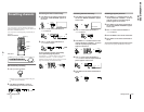
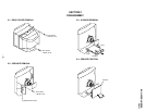
2-1. Rear Cover Removal............................................ 9
2-2. Speaker Removal ................................................. 9
2-3. A Board Removal ................................................ 9
2-4. Service Position ................................................... 9
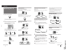
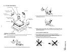
2-5. Replacement of Parts ........................................... 10
2-5-1. Replacement of Multi Button ......................................... 10
2-5-2. Replacement of Light Guide .......................................... 10
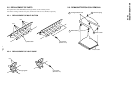
2-6. Demagnetization Coil Removal .......................... 10
2-7. Picture Tube Removal.......................................... 11
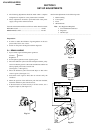
3. SET-UP ADJUSTMENTS
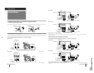
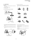
3-1. Beam Landing ...................................................... 12
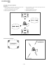
3-2. Convergence......................................................... 13
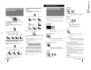
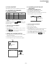
3-3. Focus Adjustment ................................................ 15
3-4. Adjustment by Commander................................. 15
3-5. G2 (Screen) and White Balance Adjustments..... 15
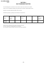
4. SELF DIAGNOSIS FUNCTION............................ 16
5. CIRCUIT ADJUSTMENTS
5-1. Adjustments with Commander ............................ 17
5-2. Adjustment Method ............................................. 18
5-3. A Board Adjustment after IC003 (Memory)
Replacement......................................................... 25
5-4. Picture Distortion Adjustment ............................. 25
6. DIAGRAMS
6-1. Block Diagram ...................................................... 27
6-2. Circuit Boards Location ....................................... 31
6-3. Schematic Diagrams and Printed Wiring Boards 31
(1) Schematic Diagram of A Board ........................... 35
(2) Schematic Diagram A of Board ........................... 39
(3) Schematic Diagrams C and VM Boards .............. 43
6-4. Semiconductors..................................................... 51
7. EXPLODED VIEW
7-1. Chassis .................................................................. 53
8. ELECTRICAL PARTS LIST.................................... 57
Section Title Page Section Title Page