


SFM1
Installation Manual Page 9
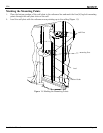
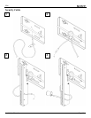
Griplates™
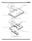
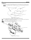
1. The Griplates™ have M4, M5, M6 and M8 hole patterns to fit the hardware that the flat panel requires.
Examples
: If your display uses M8 x 20 Phillips head screws. Use the M8 mounting points (Figure 7).
Figure 7. Griplates™ Orientation
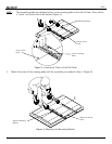
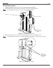
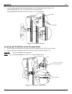
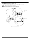
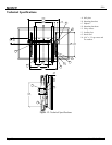
2. Once the mounting brackets are aligned, secure the Griplate™ to the flat panel.
NOTE: The dimples of the top plates have to be facing up and the bottom dimples must be facing down.
Use (1) Griplate™ per mounting point (Figure 8).
NOTE: Leave a ¾” gap on both mounting brackets as shown on this diagram.
CAUTION: Do not over tighten the mounting hardware.
DIMPLES
FACING UP
3/4"
DIMPLES
FACING UP
DIMPLES
FACING DOWN
DIMPLES
FACING DOWN
Figure 8. Griplate™ Attachment
Dimples
M
8
M
6
M
5
M
4
Phillips Screw Driver
B
ottom Flat Panel