


26 (GB)
Watching the Picture
INPUT2 (RGB) : Selects the audio and video
signal input from the INPUT2 connectors
when the input signal is an RGB signal.
INPUT2 (COMPONENT) : Selects the audio
and video signal input from the INPUT2
connectors when the input signal is a
component signal.
OPTION (VIDEO) : Selects the video signal
input from VIDEO IN on the optional
adaptor.
OPTION (S VIDEO) : Selects the video signal
input from S VIDEO IN on the optional
adaptor.
OPTION (RGB) : Selects a signal input from an
equipment connected to the RGB
connector on an optional adaptor.
OPTION (COMPONENT) : Selects a signal
input from an equipment connected to the
component connector on an optional
adaptor.
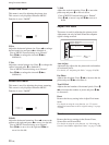
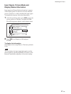
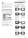
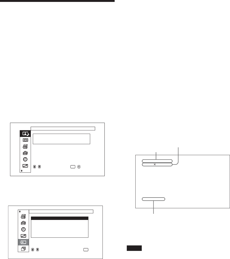
The selected input signal appears on the display
panel.
INPUT1(RGB)
1024 768/60
Standard
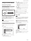
You can switch the input signal using the Remote
Commander supplied with your display.
Notes
•We recommend input source video equipment
equipped with a TBC (time base corrector). If the
display receives a signal without TBC, the picture
may disappear due to disturbance of the sync signal.
• If signals of the same format are input from multiple
systems, the Picture Quality setting will default to
the most recently set value (Only when the signal
formats are identical).
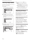
Watching the Picture
Before you start
• Turn on the display.
• Turn on the connected equipment and play a video
source.
• To display the input signal information and Picture
Mode on the screen when turning on the power or
switching the input signal, set “Display” in the
Custom Setup menu to On.
• To select the on-screen language used in the menu,
see page 38 (GB).
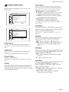
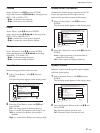
Switching the Input Signal
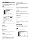
1 Press MENU.
The main menu appears on the display panel.
,toselect, ,to
ENTER
Picture/Sound Control
Picture Mode :Standard
Adjust Picture
Adjust Sound
enter adj. menu
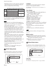
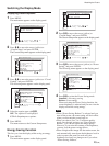
2 Press M/m to move the cursor (yellow) to “Input
Select” and press ENTER.
Input Select menu appear on the display panel.
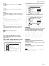
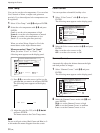
Input Select
IN P U T 1 ( RG B )
IN P U T 1 ( CO M P O N E N T )
IN P U T 2 ( RG B )
IN P U T 2 ( CO M P O N E N T )
OPTION( VIDEO)
OPTION( S VIDEO)
,toselect,press
ENTER
to execute
3 Press M/m to move the cursor (yellow) to the
input source to be displayed and press ENTER.
INPUT1 (RGB) : Selects the audio and video
signal input from the INPUT1 connectors
when the input signal is an RGB signal.
INPUT1 (COMPONENT) : Selects the audio
and video signal input from the INPUT1
connectors when the input signal is a
component signal.
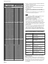
Color system or horizontal/vertical frequency
Signal type
Picture Mode