


© 2001 Robinair, SPX Corporation
10
VACUUM
VACUUM
RECOVER
RECOVER
CLOSED
CLOSED
CLOSED
CLOSED
VACUUM
VACUUM
RECOVER
RECOVER
STOP
STOP
R-134A
R-134A
in Hg
in Hg
VAC
VAC
psi
psi
kPa
kPa
bar
bar
OIL INJECT
OIL INJECT
CHARGE
CHARGE
0
0
psi
psi
kPa
kPa
bar
bar
R-134A
R-134A
0
0
4
4
5
5
3
3
0
0
0
0
5
5
2
2
0
0
0
0
0
0
4
4
0
0
0
0
0
0
0
0
5
5
3
3
START
START
MENU
MENU
8
8
0
0
CLEAR
CLEAR
7
7
ENTER
ENTER
9
9
2
2
5
5
1
1
4
4
3
3
6
6
RECOVER
RECOVER
VACUUM
VACUUM
VAC-CHARGE
VAC-CHARGE
I
I
0
0
F1
F1
CHARGE
CHARGE
0
0
0
0
8
8
0
0
0
0
1
1
2
2
3
3
0
0
0
0
1
1
2
2
0
0
5
5
3
3
0
0
0
0
0
0
3
3
0
0
0
0
1
1
0
0
2
2
0
0
1
1
2
2
0
0
E
E
R
R
0
0
4
4
8
8
2
2
T
T
A
A
R
R
D
D
0
0
8
8
0
0
7
7
8
8
6
6
4
4
3
3
0
0
4
4
0
0
0
0
0
0
5
5
5
5
0
0
0
0
4
4
6
6
0
0
0
0
0
0
6
6
7
7
0
0
0
0
0
0
0
0
1
1
0
0
1
1
0
0
1
1
0
0
0
0
0
0
7
7
0
0
1
1
0
0
0
0
5
5
0
0
1
1
0
0
0
0
5
5
0
0
1
1
0
0
0
0
9
9
5
5
0
0
2
2
0
0
0
0
1
1
0
0
0
0
0
0
4
4
3
3
5
5
0
0
5
5
0
0
1
1
0
0
0
0
0
0
3
3
2
2
5
5
0
0
2
2
0
0
0
0
5
5
1
1
5
5
2
2
2
2
0
0
5
5
0
0
0
0
3
3
HIGH
HIGH
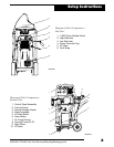
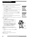
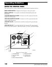
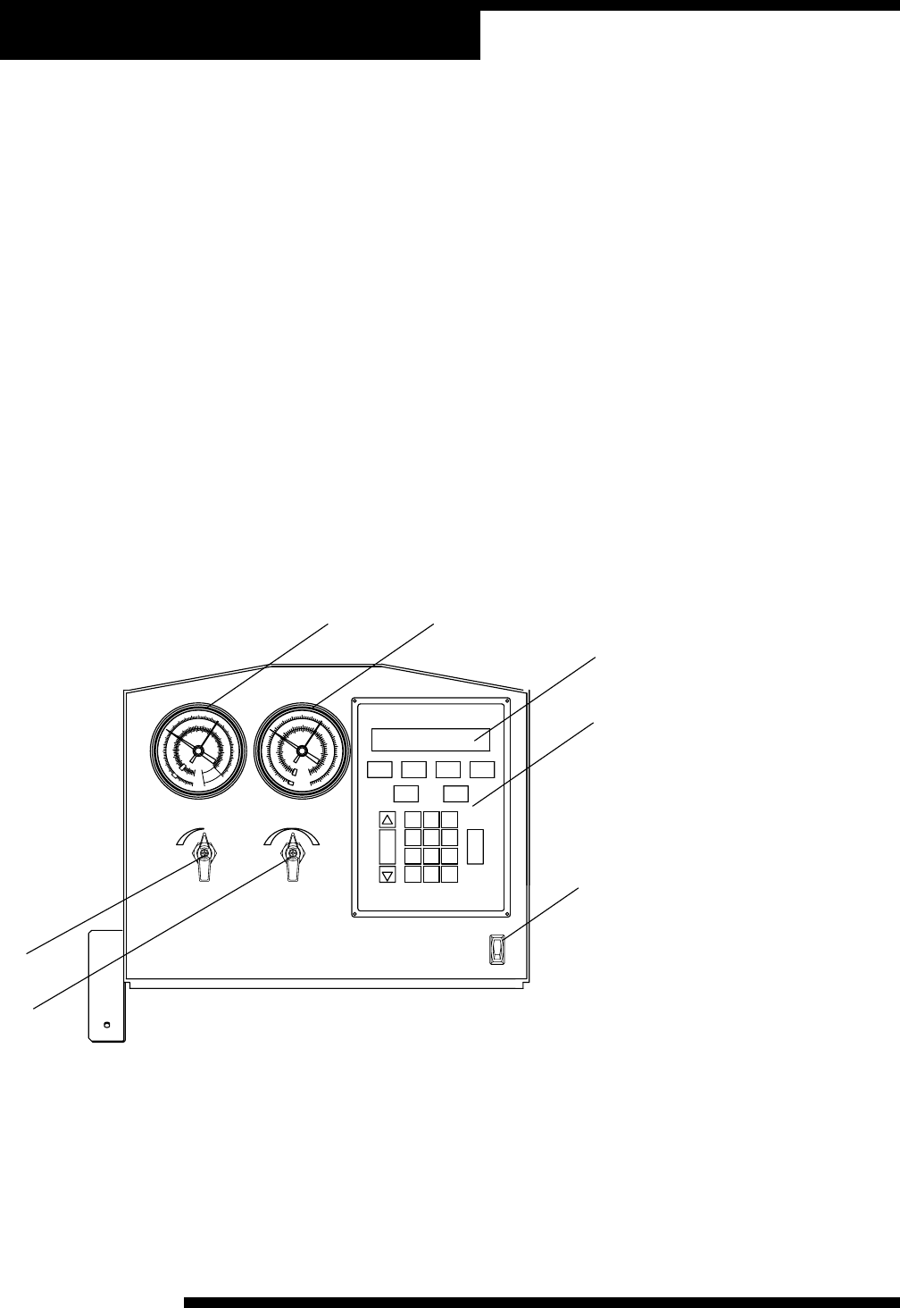
Operating Guidelines
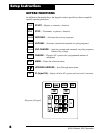
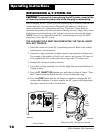
USING THE CONTROL PANEL
The control panel has various components that control specific operating functions.
MAIN POWER SWITCH—Supplies electrical power to the control panel.
DIGITAL DISPLAY—Used on the visual interface between the operator and
the machine.
LOW SIDE MANIFOLD GAUGE—Connects to an A/C system and shows the
system’s low side pressure.
HIGH SIDE MANIFOLD GAUGE—Connects to an A/C system and shows the
system’s high side pressure.
LOW SIDE VALVE—Controls the low side flow from the A/C system through
the unit.
HIGH SIDE VALVE—Controls the high side flow from the A/C system through
the unit. It has three positions: 1) Recover/Vacuum, 2) Closed, 3) Oil Inject/Charge.
5. Main Power Switch
6. Low Side Valve
7. High Side Valve
1. Low Side Gauge
2. High Side Gauge
3. Display
4. Bezel & Keypad Assembly
INST0926
1
2
3
4
6
7
Diagram of Control Panel
5